







Примерное время чтения: 14 минут
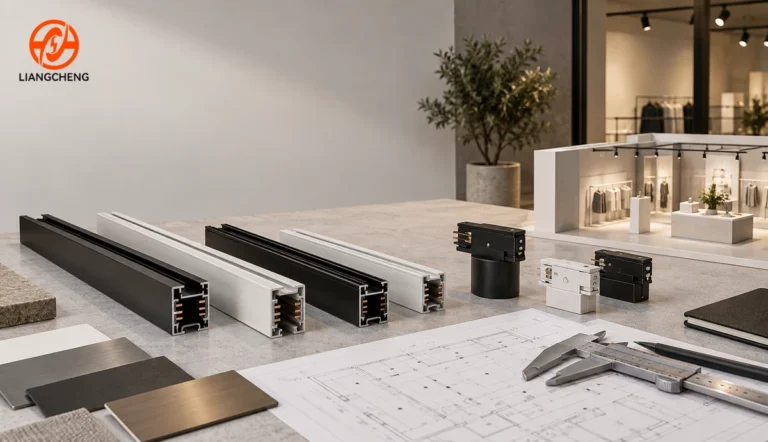
Track lighting rail accessories are the parts that feed power into a rail, join rail sections, turn or branch a layout, close exposed ends, support the installation, and connect luminaires to the conductors. A rail without the correct accessories is only an unfinished component. A complete track lighting system must coordinate the rail profile, electrical interface, connector orientation, mounting method, fixture adapter, ratings, finish, and installation plan.
This guide explains accessories as a working system rather than as a catalog of isolated parts. It is written for distributors, lighting brands, contractors, specifiers, and purchasing teams that need to convert a ceiling layout into an accurate bill of materials. If you first need a basic explanation of the rail itself, start with this introduction to LED lighting track. The sections below focus on what each accessory does, where it belongs, how quantities are calculated, and what must be verified before an order is approved.
What accessories make up a complete track lighting rail system?
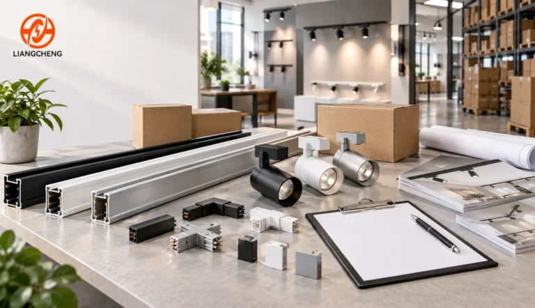
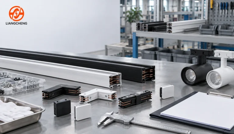
A complete accessory schedule normally includes five functional groups: power-entry parts, rail-to-rail connection parts, directional layout connectors, termination parts, and mounting or suspension hardware. Fixture adapters form a sixth group because they create the mechanical and electrical interface between each luminaire and the rail. Some projects also need circuit-selection, data, or control components, but those items are system-specific and should never be assumed to be universal.
| Accessory group | Typical parts | Main job | Primary risk if mismatched |
|---|---|---|---|
| Power entry | Live-end feed, center feed, cable-entry box | Connects the branch circuit to the track conductors | Wrong polarity, circuit mapping, or rating |
| Straight connection | Electrical joiner, mechanical joiner | Extends a run and maintains alignment | Loss of continuity or a weak joint |
| Directional connection | L, flexible, T, and X connectors | Turns, branches, or intersects the layout | Wrong handedness or conductor orientation |
| Termination | End cap, blanking cover | Closes and protects an unused end | Exposed edge or accessible internal parts |
| Mounting | Screws, clips, brackets, recessed wings, suspension kits | Transfers the rail load to the building structure | Poor alignment or inadequate support |
| Fixture interface | Track adapter, pendant adapter, circuit selector | Locks a luminaire into the rail and makes contact | A fixture that fits physically but does not work safely |
The important purchasing lesson is that a single accessory name does not prove interchangeability. Two straight joiners may look similar while using different contact spacing, locking features, grounding arrangements, or circuit paths. Every accessory should be specified within one confirmed track family.
How do power feeds connect the building supply to the rail?
A power feed is the controlled entry point between field wiring and the conductive paths inside the rail. The most common version is a live-end feed installed at one end of a run. A center feed, sometimes described as an inline feed, can supply two rail directions from a point between sections. Projects may also use feed boxes or covers that provide wiring space and a finished transition at the ceiling.
The feed must match the conductor count in the rail, circuit arrangement, profile, protective-earth design where applicable, and rated voltage and current. Orientation matters because many conventional track families are polarized. The feed and rail may include a visual key, raised edge, contact pattern, or internal feature that establishes the correct side. Reversing a directional feed or forcing it into an unmatched profile can map conductors incorrectly or damage contacts.
The drawings should identify where building power enters each run, how many independently controlled circuits are required, and whether the feed has enough space for the specified cable and termination method. A long layout is not automatically served correctly by adding rail length; an electrical designer must confirm circuit loading, voltage drop where relevant, protective devices, and local installation requirements. The accessory list should follow that approved electrical design.
What is the difference between electrical and mechanical joiners?
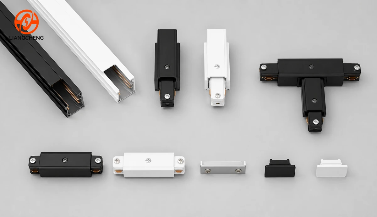
An electrical straight joiner extends both the physical rail and the conductive paths. It must keep the sections aligned while transferring the intended circuits across the joint. A mechanical joiner or alignment plate may strengthen or align a connection without carrying power. Some systems combine both functions in one part, while others require separate pieces.
This difference affects the bill of materials. If two rail lengths meet and electrical continuity is required, a purely mechanical connector is not enough. If a special mounting condition creates a structural joint, an electrical connector alone may not provide the support intended by the system design. The product drawing and installation instruction should state which function each part performs.
For every straight joint, check the insertion depth and resulting layout length. The nominal rail lengths alone do not always equal the finished end-to-end dimension. Connector bodies, feed housings, end clearances, and field cuts can change the installed result. Buyers planning exact ceiling grids should use the measurement process in the руководство по размерам направляющих для трекового освещения and obtain dimensioned accessory drawings before finalizing the ceiling opening or suspension positions.
When should a layout use L, flexible, T, or X connectors?
Directional connectors translate the geometry of the reflected ceiling plan into a continuous rail network. An L connector makes a right-angle corner. A flexible connector joins runs at a variable angle or bridges a change in plane when the product is designed for that use. A T connector creates a three-way branch. An X connector creates a four-way intersection. A simple straight joiner should be used when no turn or branch is required.
The outline of a connector does not reveal its electrical routing. On polarized or multi-circuit systems, an L or T connector can have a specific inside and outside orientation. T connectors may be available in different handed configurations because the conductor sequence must remain consistent through the branch. Rotating a connector in the drawing is not always electrically equivalent to ordering the opposite version.
Mark each connector on the plan with a unique reference, an orientation arrow, the rail family, finish, and circuit-routing requirement. For complex layouts, add a small enlarged detail at every T or X point. This prevents a purchasing team from counting only shapes while missing handedness. It also gives installers an unambiguous reference when parts are delivered to the site.
Why are end caps and covers required?
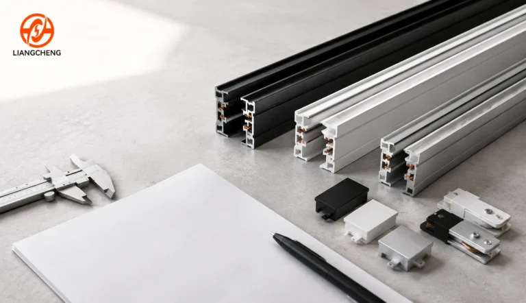
An end cap closes the open end of a track section. It improves the finished appearance, protects the rail edge, and helps prevent unintended access to internal components. It is a termination part, not a power feed and not a joiner. Every open run end that is not occupied by another approved accessory normally needs the matching cap.
End caps are easy to omit because they are small and do not influence the visible lighting effect. However, a missing cap can delay handover, create a visibly unfinished installation, or require a separate shipment that costs far more than the part. Count open ends after the entire layout has been divided into runs, branches, feeds, and joints. Do not estimate end caps as a percentage of rail quantity.
How do fixture adapters affect system compatibility?
The track adapter is the interface between a luminaire and the rail. It provides the mechanical lock, positions the contacts against the conductors, and may include a circuit selector or other system-specific function. A fixture body can be electrically suitable in principle yet remain incompatible because its adapter does not match the rail geometry.
Compatibility requires more than the same number of wires. Verify the rail cross-section, adapter width and keying, contact number and positions, grounding feature, locking method, polarity, ratings, and circuit-selection logic. A product that slides into the opening is not necessarily a confirmed match. The detailed 3-wire rail and track light compatibility guide explains this interface-first approach.
Distributors should treat the rail, adapter, and luminaire as an approved set. Request assembled samples and cycle the adapter through insertion, locking, circuit selection where present, energizing under an approved test setup, and removal. Check for secure retention, consistent contact pressure, smooth operation, and no abnormal marks. If multiple fixture factories will supply luminaires for one rail program, approve every adapter source against the same controlled rail sample.
Which mounting accessories are needed for surface, recessed, and suspended rails?
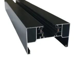
Mounting accessories transfer the system load to the building structure while preserving straightness and alignment. Surface-mounted rail may use holes in the profile, screws, anchors, clips, or brackets specified by the manufacturer. Recessed rail can require trim, flanges, wings, bridging brackets, or a compatible ceiling channel. Suspended rail generally needs ceiling canopies, cables or rods, grippers, rail brackets, and sometimes separate power-drop hardware.
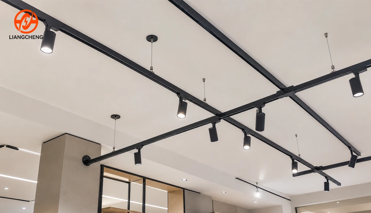
The mounting method changes the accessory schedule even when the electrical rail family is unchanged. A suspended rectangle, for example, needs support points distributed around the perimeter and coordinated around corners and connectors. A recessed run needs accurate ceiling cutouts and enough access for feeds and joins. A surface run needs fasteners appropriate for the substrate. The rail accessory supplier can define compatible system parts, but the project engineer or installer must confirm the structure, anchors, spacing, seismic or local requirements, and total supported load.
Are control accessories universal across track systems?
No. Circuit selectors, control adapters, data conductors, sensor modules, and dimming interfaces depend on the exact track architecture. A single-circuit conventional rail, a multi-circuit rail, and a system that carries control conductors solve different problems. Similar exterior dimensions do not prove that their internal wiring or accessories are compatible.
Start by defining the control intent: all luminaires switched together, several independently switched groups, individually addressed luminaires, or a separate building-control method. Then select the rail and adapter family that supports that intent. The single-circuit versus multi-circuit comparison helps clarify the difference between grouping flexibility and the physical parts required to deliver it.
How can buyers verify that every accessory belongs to the same system?
Use an interface control checklist. The checklist should compare the rail and every mating accessory against a controlled drawing, approved sample, or both. This is more reliable than ordering from appearance, a generic product name, or conductor count alone.
| Check | What to compare | Acceptance evidence |
|---|---|---|
| Profile geometry | Overall width and height, internal keying, slot opening, wall features | Dimensioned drawing and sample fit |
| Electrical interface | Contact positions, conductor mapping, polarity, grounding arrangement | Wiring diagram and continuity test |
| Mechanical lock | Insertion direction, latch engagement, retention, screw locations | Assembly trial and pull or retention check as specified |
| Ratings | Voltage, current, temperature, fixture load, applicable approvals | Product specification and required documentation |
| Orientation | Left/right feed, inside/outside corner, T branch direction | Marked plan and part code |
| Завершить | Color, gloss, texture, coating coverage | Approved color sample or limit sample |
The terms used for track families can vary by market, and labels such as H, J, or L are not substitutes for checking the actual interface. When those market names are relevant, consult the H-type, J-type, and L-type compatibility guide, then confirm the project with drawings and physical samples.
How do you convert a ceiling layout into an accessory BOM?
Begin with the approved reflected ceiling plan, not a total number of meters. Divide the design into continuous rail segments and mark every place where power enters, rail sections meet, direction changes, a branch starts, a run ends, a luminaire connects, or the mounting method changes. Each marked event creates one or more BOM lines.
- Identify the rail family. Record conductor or circuit configuration, profile, installation type, finish, and standard or cut lengths.
- Number every run. Give each continuous path a run code so that parts can be packed and checked by area.
- Mark feeds. Count live-end feeds, center feeds, feed boxes, cable covers, and power drops from the electrical plan.
- Mark joints. Count straight electrical and mechanical joiners based on how stock lengths are combined.
- Mark geometry. Assign the exact orientation and part code to every L, flexible, T, or X connector.
- Count open ends. Add the correct end cap for each exposed termination.
- Calculate supports. Apply the mounting guidance from the manufacturer and the structural requirements of the project to each run and connector area.
- Count adapters. Match one approved adapter to every fixture, pendant, or special attachment, plus agreed spares.
For example, two straight rails joined into one powered run with no branches commonly create one feed point, one straight joint, and one open terminal end. The exact list may include both an electrical joiner and a separate mechanical alignment part. An L-shaped run made from two sections adds a directional connector instead of a straight joiner. A T layout adds a three-way connector whose orientation must match the conductor path. These examples are counting logic, not universal product recipes; the chosen system drawing remains the authority.
What information should an accessory schedule contain?
An effective schedule is specific enough for quotation, production, packing, installation, and inspection. Include a line number, part name, supplier part code, rail family, electrical function, orientation, color or finish, quantity, spare quantity, drawing revision, destination area, and any required document. Add a small thumbnail or diagram for directional parts when similar codes can be confused.
Keep sets visible as separate components. The phrase complete accessories is too vague for a commercial order because the buyer and supplier may count different items. The schedule should state whether screws, anchors, cover plates, suspension canopies, cables, feed boxes, adapters, selectors, and end caps are included. It should also identify what is provided by the installer rather than the rail supplier.
How should accessories be packaged for wholesale and project orders?
Small parts need a packaging strategy because they are easy to mix, scratch, or lose. Separate accessories by part code, color, and orientation. Label the inner bag and outer carton consistently with the BOM. For project orders, consider packing by floor, zone, shop, or run code so the installer receives a usable kit rather than a mixed carton.
What should be inspected before bulk accessories are accepted?
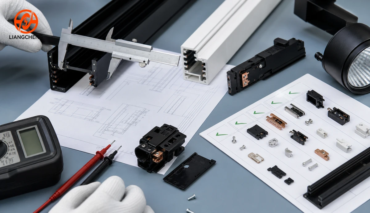
Incoming inspection should verify identity, quantity, finish, dimensions, assembly, and electrical function at a level appropriate to the order and quality plan. Begin by matching cartons and inner labels to the purchase order. Confirm left/right or directional variants separately. Compare color and gloss with the approved limit sample under consistent lighting.
Measure critical interface dimensions rather than only overall size. Trial-fit feeds, joiners, corners, end caps, and adapters with retained rail samples. Check that latches engage, screws align, caps seat fully, and connectors do not create obvious steps or gaps. Perform continuity and conductor-mapping checks with the system disconnected and under the approved test procedure. Any energized testing should be performed by qualified personnel using suitable equipment and safeguards.
How many spare accessories should a project order?
There is no universal spare percentage for every accessory. Base the quantity on part criticality, risk of loss or damage, lead time, future layout changes, and the number of identical locations. Low-cost end caps, mounting pieces, and common straight joiners often justify practical site spares. Rare handed T connectors or custom-color feeds may justify at least one clearly labeled replacement when a failure would stop commissioning.
What are the most common accessory specification mistakes?
- Buying by appearance: similar housings can hide incompatible contacts, keys, or circuit paths.
- Counting rail meters only: total length does not reveal feeds, joints, corners, branches, ends, or support points.
- Ignoring connector orientation: an L or T part may be electrically directional even when the outline can be rotated on a plan.
- Confusing mechanical and electrical joins: alignment does not prove continuity, and continuity does not automatically satisfy structural support requirements.
- Approving fixtures before adapters: the adapter determines whether the luminaire can connect to the selected rail.
- Mixing finishes late: black or white parts from different batches can vary in texture or gloss.
- Using generic BOM language: one unspecified set of accessories cannot be inspected or packed reliably.
- Skipping a pilot layout: a small assembled sample can expose interface and orientation problems before bulk shipment.
These errors are especially costly on commercial projects because one missing connector can stop an entire run. For a wider view of coordination, documentation, and buying decisions beyond accessories, see the commercial track lighting rail systems guide.
Frequently asked questions about track lighting rail accessories
Can accessories from different track rail suppliers be mixed?
They should not be mixed based on appearance or a generic family name. Mixing is acceptable only when the exact profile, electrical mapping, lock, ratings, orientation, and required documentation have been verified and the combination has been approved for the project.
Does every rail joint need an electrical connector?
An electrical connector is needed when power or circuit continuity must pass across that joint. Some systems also require a separate mechanical alignment part. A deliberate isolation point may use a different component. Follow the system drawing rather than assuming every visible joint performs the same function.
Can a rail be cut on site without changing the accessory list?
Cutting changes segment lengths and may create a new open end, joint, or feed location. The cut must be allowed by the product instructions, performed correctly, cleaned, and inspected. Update the layout and BOM whenever field cuts change terminations or connections.
What information is needed for an accurate quotation?
Provide the rail type, profile or drawing, circuit requirement, mounting method, color, rail lengths, layout with connector orientations, fixture and adapter count, quantities, packing preference, destination market, required documents, and customization needs. A marked ceiling plan is much more useful than a total rail length alone.
How can Liangcheng Lighting support a complete accessory program?
Liangcheng Lighting supplies aluminum track rail systems for wholesale, distributor, lighting-brand, and commercial project requirements. The available range includes conventional rail configurations and matching accessories such as connectors, end caps, power feeds, suspension kits, and mounting parts. Buyers can also discuss OEM and ODM requirements including custom lengths, colors, surface finishes, packaging, branding, and project-specific system coordination.
A productive inquiry should include the target market, track family, layout drawing, circuit plan, fixture adapter, finish, order volume, and required delivery format. The Liangcheng team can then review the accessory schedule as a coordinated system instead of quoting rail meters in isolation. For programs that need differentiated sizes, finishes, or packaging, the custom track rail solutions guide explains the broader OEM and ODM process.
Planning a wholesale range or commercial track lighting project? Contact Liangcheng Lighting through the aluminum track lighting rail product page and send your drawing, rail specification, accessory list, fixture adapter details, and expected volume. The team can help prepare a compatible track rail and accessory proposal for sampling, private-label development, or bulk supply.
Нужны индивидуальные решения для трекового освещения?
Свяжитесь с Liangcheng Lighting для получения решений OEM/ODM по алюминиевым трековым системам и профессиональной светотехнической поддержке.