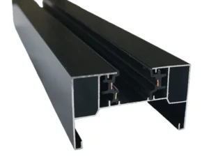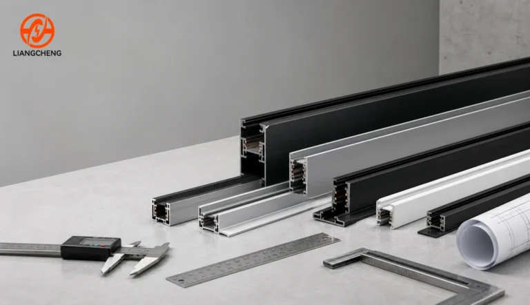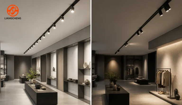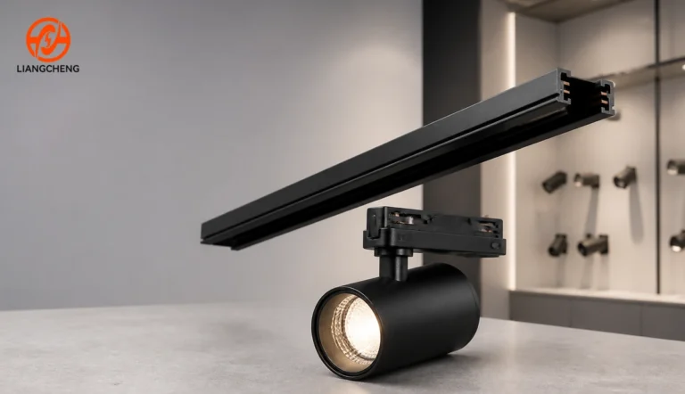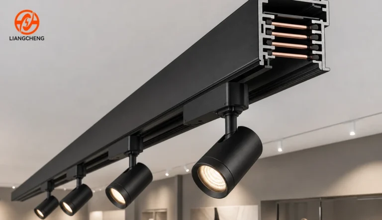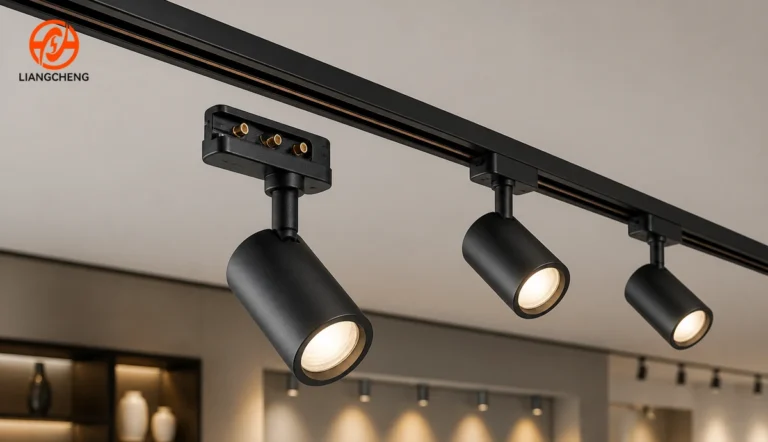







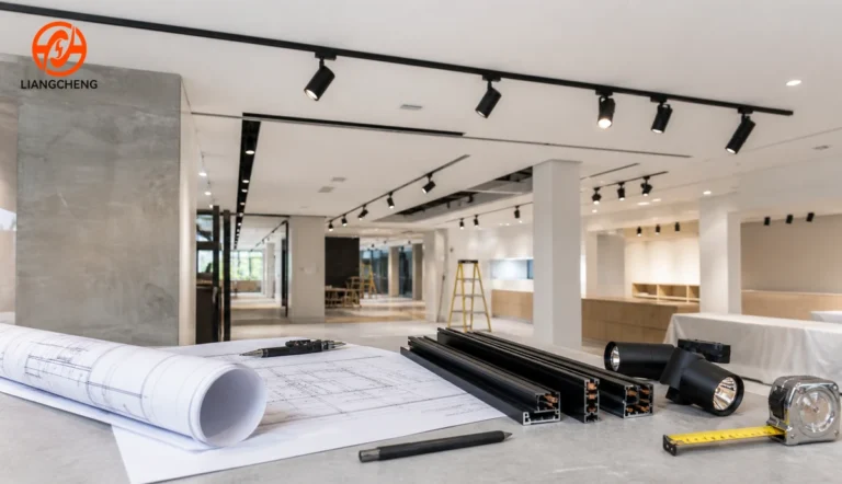

Choosing the right track rail starts with the lighting project, not with the rail catalog. Define what must be illuminated, how the light will be controlled, where the rail can be mounted, and which luminaires must connect to it. Then select one complete system whose rail, adapters, feeds, connectors, electrical ratings, and installation method are compatible. A simple single-circuit rail can be the best choice for one switching group, while a multi-circuit or magnetic system may be justified when the project needs separate scenes, a different visual language, or more reconfiguration options.
Estimated reading time: 14 minutes.
This guide uses a project-first selection method. It does not repeat every conductor type, profile dimension, or adapter format already covered in our technical guides. Instead, it shows how to turn a lighting brief into a rail specification, how to eliminate incompatible options, and what to verify before placing an order.
What should you decide before choosing a track rail?
Before comparing products, answer six project questions: What lighting tasks must the system perform? How many control groups are needed? Is the installation new or a retrofit? What mounting method and ceiling conditions apply? Which luminaire family will be used? Which electrical and regulatory requirements apply in the destination market?
| Project question | Why it changes the rail choice | Evidence to collect |
|---|---|---|
| What needs to be illuminated? | Display, circulation, wall washing, and general lighting require different fixture positions and layout flexibility. | Reflected ceiling plan, furniture plan, target surfaces, and lighting calculations |
| How should the lights be controlled? | One switching group may suit a single circuit; independent zones may require multiple circuits or another control architecture. | Scene schedule, switch zones, dimming method, and control diagram |
| How will the rail be installed? | Surface, recessed, and suspended installations have different profiles, accessories, clearances, and coordination needs. | Ceiling section, substrate, mounting height, and available void depth |
| Which fixtures will be used? | The mechanical key, contact position, voltage architecture, and adapter must match the rail family. | Fixture and adapter drawings, samples, and supplier compatibility statement |
| What is the complete run geometry? | Feeds, end caps, straight joints, corners, and suspension points affect both length and ordering quantity. | Dimensioned layout with every feed, joint, turn, and termination marked |
| What must be approved locally? | Electrical ratings, installation practices, and documentation vary by market and project. | Local code requirements, project specification, and approval documents |
The best rail is therefore not the profile with the most conductors or the largest cross-section. It is the least complicated system that meets the design, control, installation, compatibility, and compliance requirements with a reasonable margin for future change.
Step 1: Convert the lighting concept into practical tasks
Begin with the surfaces and activities that need light. A fashion display may need narrow accent beams that move when merchandise changes. An art wall may need even vertical illumination. A reception desk may combine task and decorative lighting. A corridor may need a straightforward row of fixtures with one control group. These are different problems even when all four projects use black track on a white ceiling.
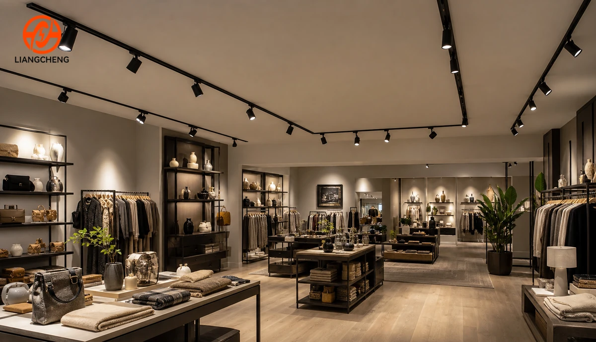
Mark the likely luminaire positions on the reflected ceiling plan and test whether each head can aim at its target without extreme rotation or visual clutter. Also consider what may move later. Retail gondolas, gallery displays, restaurant tables, and exhibition walls can change frequently. A rail run placed only for today’s furniture layout may lose much of its value after the first rearrangement.
Use lighting calculations or a mock-up to determine fixture output, beam angle, spacing, and aiming. The rail distributes power and provides a mounting path, but it does not determine the quality of light by itself. Our explanation of the difference between a track rail and a track light is useful when responsibilities are being divided between the ceiling system and the luminaires.
Step 2: Choose the system architecture before the detailed profile
The first major filter is whether the project needs a conventional line-voltage track family or a magnetic system with its own rail, power, and fixture architecture. These systems are not interchangeable. Conventional systems commonly use mechanical adapters that lock into an energized rail. Magnetic systems use a different attachment method and may use a separate low-voltage power architecture, depending on the product design.
Choose based on the complete project, not appearance alone. Conventional track can be a practical choice when the project needs familiar spotlight formats, direct and straightforward installation, or easy access to higher-output fixture options. A magnetic system may suit a design that values a slim visual line, frequent tool-free fixture changes, or a family of compact linear and spot modules. The article on ordinary and magnetic track lighting examines that system-level decision in more detail.
Do not mix the two architectures in one specification unless the lighting design intentionally uses two independent systems and clearly separates their components. A magnetic luminaire cannot be made compatible with a conventional rail merely because the fixture is physically small enough to fit near it.
Step 3: Translate lighting scenes into circuit and control requirements
Next, decide how many groups of luminaires must be controlled independently on each rail run. A small room in which every track head switches together may need only one circuit. A retail run may need separate groups for perimeter displays, center fixtures, and promotional zones. A hospitality project may need different scenes for daytime service, evening ambience, cleaning, and events.
Write the scene schedule before choosing the conductor configuration. This prevents a common mistake: selecting a rail with more wires because it sounds more flexible, without confirming how those conductors are assigned or how the adapters select a circuit. Wire count, circuit count, grounding arrangement, neutral arrangement, dimming, and digital control are related design questions, but the terms are not automatic substitutes for one another.
For a focused comparison, see single-circuit vs multi-circuit track lighting. If the procurement team is comparing conductor formats, the separate 2-wire, 3-wire, and 4-wire track guide explains why the label alone does not prove circuit behavior or compatibility.
Confirm how dimming will work as part of the complete control design. A rail can distribute power to a compatible adapter, but dimming also depends on the driver, control signal, wiring topology, and control equipment. A multi-circuit rail does not automatically provide individual fixture addressing, and adding more circuits does not automatically reduce energy use.
Step 4: Match the mounting method to the ceiling and architecture
Surface-mounted rail is often the simplest to coordinate because the profile remains visible and attaches to an appropriate substrate. It can suit finished ceilings, renovations, and industrial-style interiors. Recessed rail can produce a more integrated ceiling line, but it requires accurate cutouts, flange or trim coordination, sufficient void depth, and a plan for maintaining feeds and connectors. Suspended rail can lower the lighting plane below a high or open ceiling, but it adds suspension spacing, cable management, stability, and visual alignment requirements.
Do not select recessed rail from the visible width alone. The installer needs the complete profile drawing, including total body width, flange width, cutout, depth, fastening zones, connector envelope, and any driver or feed access. Similarly, a suspended layout needs the allowable suspension method and spacing for the specific system, not a generic assumption based on rail length.
Our track lighting rail dimensions guide provides a measurement and drawing checklist. For every mounting method, the project team should also verify the ceiling substrate, fixing method, coordination with sprinklers and air diffusers, access for electrical work, and local installation requirements.
Step 5: Design the complete run, not just the straight rail
A track run is a system of straight lengths, feeds, joints, corners, end caps, mounting parts, and luminaires. Draw every piece before calculating quantities. Mark where power enters, where the rail changes direction, where two lengths join, and where the run terminates. If a connector has an orientation or electrical polarity, show that orientation on the plan.
Standard stock lengths can often be cut, but cutting rules depend on the product. The finished run length is not simply the room dimension divided by a nominal rail length. Connector engagement, end clearance, field cuts, structural joints, feed space, and installation tolerance all affect the result. Long runs may also require more than one mechanical support point and careful alignment at each joint.
Keep a connector schedule beside the reflected ceiling plan. Count left and right corners separately if the connector family is directional. Confirm whether straight couplers are mechanical only or also continue the electrical paths. For a multi-circuit system, the connector must preserve the intended circuit assignment through the whole run.
Step 6: Check electrical capacity and project rules
Electrical selection should be completed or reviewed by a qualified professional for the project location. Verify the system voltage and frequency, conductor and circuit ratings, protective device, grounding method, maximum connected load, allowable continuous loading rules, inrush behavior where relevant, and the ratings of feeds and connectors. Use the lowest applicable rating in the assembled path rather than assuming the rail body determines the capacity of every component.
Create a load schedule for each circuit. List the fixture quantity, rated input power, driver characteristics, and expected future additions. Leave only a justified design margin; do not treat unused physical rail length as proof of electrical capacity. If emergency lighting, centralized control, or special building systems are involved, coordinate those requirements separately instead of assuming a standard track circuit can perform every function.
Documentation should match the destination market and the actual ordered model. A general certificate, test report, or declaration is not useful if it covers a different rail family or excludes a critical adapter. Ask the supplier to identify model numbers on drawings, quotations, packing lists, and supporting documents consistently.
Step 7: Treat compatibility as a system approval
Two rails can look similar and still reject each other’s fixtures. Compatibility depends on the rail’s mechanical key, internal geometry, conductor location, adapter dimensions, contact arrangement, voltage architecture, grounding, circuit selection method, and accessory family. Matching width, color, contact count, or a familiar type label is not enough.
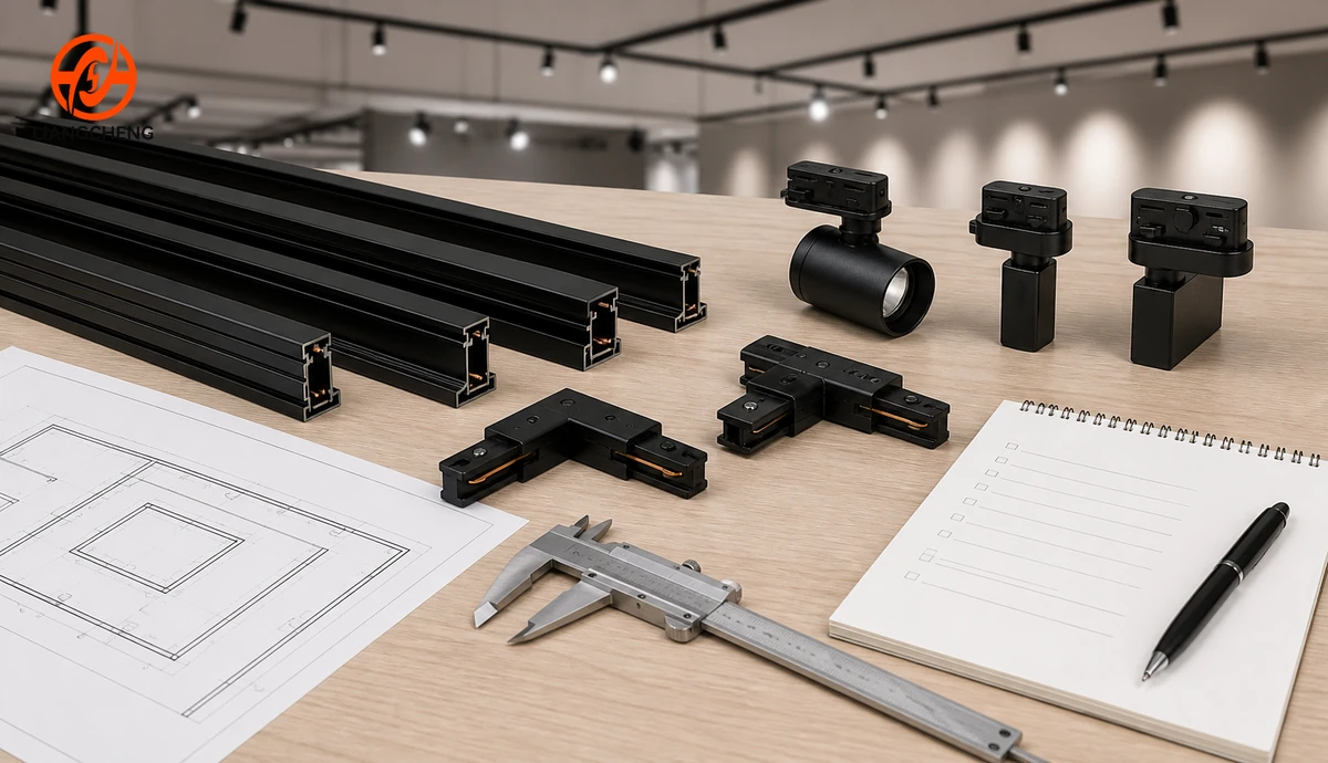
For an existing installation, identify the current rail before ordering replacement heads. Record the manufacturer and model if available, photograph the opening and contacts, measure the profile, check the supply and grounding arrangement, and test a physical sample. Regional interface labels can be helpful clues, but they should not replace dimensional and functional verification. The H-Type, J-Type, and L-Type compatibility guide explains why similar-looking track families should not be assumed interchangeable.
For a new project, the simplest procurement rule is to approve one coordinated family. Obtain rail sections, the exact fixture adapters, all planned connectors, feeds, and end parts from a confirmed compatible system. If different suppliers are involved, require written compatibility confirmation and conduct a sample assembly test before approving the production order.
Step 8: Evaluate material, finish, and construction details
After the system architecture is correct, compare the physical construction. Review the aluminum profile, profile straightness, wall consistency, insulation supports, conductor retention, surface finish, joint fit, and adapter locking action. Material labels are only a starting point. Workmanship and dimensional control determine whether long runs align cleanly and whether repeated fixture changes remain reliable.
Choose the finish using real project samples. Black, white, and metallic finishes can look different under warm and cool lighting, and gloss level changes how visible a ceiling line becomes. For humid, coastal, dusty, or otherwise demanding environments, ask whether the complete system is suitable for the actual conditions. Do not infer environmental protection from an aluminum housing alone; connectors, contacts, adapters, fasteners, and fixtures also matter.
Mechanical loading needs a product-specific review. The rail must support the intended luminaires when installed with the specified fixing method and spacing, but profile width by itself does not establish load capacity. Heavy pendants, long suspended runs, vibration, accessible public areas, or unusual mounting angles require explicit engineering confirmation.
Step 9: Build a complete bill of materials
A correct rail description can still produce an incomplete order. Prepare a bill of materials for each run and link every line item to the ceiling plan. At minimum, include:
- rail model, conductor or circuit configuration, mounting type, finish, and length;
- power feeds with entry direction and circuit configuration;
- straight, L, T, flexible, or other required connectors with orientation;
- end caps, recessed trims, suspension kits, and mounting hardware;
- track heads or other luminaires with exact adapter models;
- drivers, transformers, control interfaces, or remote power components when the system requires them;
- spares for site cuts, connectors, end caps, and the agreed maintenance strategy;
- drawings, installation instructions, and approval documents tied to the ordered model numbers.
Use one naming convention across the drawing, quotation, sample approval, and purchase order. Terms such as “three wire,” “three line,” and “three circuit” can be interpreted differently. A model number plus an approved drawing is safer than a short verbal description.
Step 10: Validate the system before the full order
A representative sample assembly is one of the most useful procurement checks. The sample should include a rail section, a power feed, each connector type, the exact luminaire adapters, and at least one fixture from every planned family. For a custom color or profile, the sample should also represent the approved material and finish.
Check mechanical fit, adapter locking, contact engagement, circuit selection, grounding continuity where applicable, joint alignment, finish consistency, and fixture movement. Have the appropriate qualified personnel conduct electrical tests. If the project includes dimming, scene control, emergency functions, or remote power equipment, test that architecture as a system rather than approving the rail in isolation.
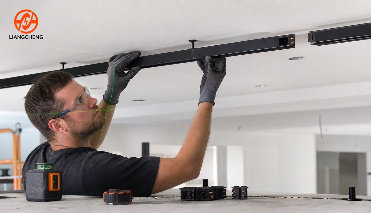
For a large project, add a first-article or mock-up approval before mass installation. Build one representative run in the actual ceiling condition, aim the fixtures, commission the controls, and review the appearance with the designer and client. Record approved samples and corrections so that later deliveries can be checked against the same reference.
Which track rail suits different project situations?
| Project situation | Likely starting point | What could change the recommendation |
|---|---|---|
| Small room with one lighting scene | Simple single-circuit conventional rail | Need for separate display and general lighting groups, special controls, or a different fixture family |
| Retail store with changing displays | Rail layout with adequate repositioning and planned control zones | Merchandise density, wall-wash needs, future floor plans, and maintenance access |
| Gallery or showroom | Flexible aiming, compatible optical options, and carefully planned rail positions | Exhibition changes, ceiling height, glare control, conservation requirements, and scene control |
| Hospitality interior | System coordinated with decorative intent and scene schedule | Dimming quality, ceiling integration, fixture visibility, and maintenance hours |
| Retrofit using existing rail | Identify and verify the installed system before buying fixtures | Unknown interface, damaged contacts, unavailable components, or noncompliant existing work |
| High or open ceiling | Surface or suspended system reviewed for mounting height and access | Structure, suspension stability, fixture output, aiming, and future maintenance equipment |
These are starting points, not universal prescriptions. A small project can need sophisticated control, while a large warehouse-style retail area may work well with simple switching zones. The project brief should determine complexity.
What common selection mistakes should you avoid?
Choosing by wire count alone
A conductor label does not fully define the number of usable control groups, interface, grounding, or dimming architecture. Verify the circuit diagram and adapter behavior.
Assuming similar rails are interchangeable
Similar cross-sections can hide different keys and contact positions. Approve an actual rail-adapter-fixture combination.
Designing only the straight lengths
Missing feeds, directional corners, couplers, end caps, trims, or suspension parts can stop an installation even when the correct rail has arrived.
Choosing the rail before the lighting tasks
A rail cannot correct the wrong fixture distribution, beam angles, control zones, or mounting positions. Complete the lighting concept first.
Leaving control decisions until installation
Circuit allocation, dimming, and scene control affect wiring, adapters, drivers, feeds, and commissioning. Late changes often require more than a switch replacement.
Skipping samples because drawings look correct
Drawings are essential, but a physical test can reveal tolerances, locking behavior, joint alignment, finish differences, and connector access that are difficult to judge on paper.
What information should a track rail specification include?
A useful specification should identify the system without depending on ambiguous shorthand. Include the system architecture, rail model, profile drawing revision, mounting type, circuit or conductor configuration, electrical ratings, finish, stock and cut lengths, feeds, connector types and orientations, end parts, suspension or fixing method, fixture adapter model, compatible luminaire schedule, control architecture, required documentation, packaging, sample approval, and inspection criteria.
Also state who is responsible for electrical design, structural fixing, ceiling coordination, field cutting, commissioning, and final acceptance. These responsibilities are project matters, not merely product features. If a standard product cannot meet the ceiling, finish, length, or system requirements, review a custom LED track rail solution only after the functional brief is stable.
Final track rail selection checklist
- Define the illuminated surfaces, fixture types, aiming positions, and expected layout changes.
- Choose conventional or magnetic architecture as a complete system decision.
- Write the switching, dimming, and scene requirements before selecting circuit configuration.
- Confirm surface, recessed, or suspended mounting against the real ceiling section.
- Dimension every rail run and mark feeds, joints, corners, terminations, and access points.
- Calculate each circuit load and verify ratings, protection, grounding, and local requirements.
- Approve rail, adapters, luminaires, and connectors as one compatible family.
- Review construction quality, finish samples, environment, and mechanical loading.
- Create a model-specific bill of materials linked to the drawings.
- Test a representative sample or mock-up before full production and installation.
Frequently asked questions
Is a multi-circuit track rail always better?
No. Multi-circuit rail is useful when one run must support independently controlled groups. If all fixtures operate together, a simpler single-circuit system may be easier to specify, install, and maintain.
Should I choose the track rail or the track lights first?
Define the lighting tasks and fixture performance first, then choose a compatible rail and adapter family together. Do not buy either component independently when the interface has not been verified.
Can track rail be cut on site?
Many systems allow field cutting, but the permitted method, minimum length, conductor treatment, end preparation, and warranty conditions are product-specific. Follow the approved instructions and include cut allowances in the quantity plan.
Can I use different fixture styles on one rail?
Yes, if every fixture uses an adapter approved for that exact rail family and if the electrical, circuit, control, and loading requirements are satisfied. Physical insertion alone is not proof of safe compatibility.
How much spare capacity should a project include?
Reserve capacity should come from a documented future-use scenario and the applicable electrical design rules. Do not add fixtures until the circuit load, driver behavior, connectors, feeds, and protection have been checked.
What is the safest way to replace an unknown existing rail?
Record the installed model and supply information, inspect the rail condition, measure the interface, and test a confirmed sample. If the system cannot be identified or has damaged components, a coordinated replacement may be safer and more predictable than mixing old and new parts.
Final answer
To choose the right track rail for a lighting project, work from requirements to hardware. Define the lighting tasks, scenes, ceiling conditions, run geometry, electrical limits, and fixture family. Then approve one compatible rail system, document every accessory in the bill of materials, and validate it with a sample or mock-up. This approach avoids the two most expensive errors in track lighting procurement: selecting a rail that cannot deliver the intended control strategy and ordering components that appear compatible but do not function as one system.
Нужны индивидуальные решения для трекового освещения?
Свяжитесь с Liangcheng Lighting для получения решений OEM/ODM по алюминиевым трековым системам и профессиональной светотехнической поддержке.