








Estimated reading time: 13 minutes
Single-circuit track lighting controls all compatible fixtures on a rail run as one electrical group. When that circuit is switched or dimmed, every fixture assigned to it responds together. Multi-circuit track lighting provides two or more selectable electrical groups within a coordinated rail system, so fixtures sharing one physical track route can be assigned to different switching or dimming groups.
The core difference is therefore control segmentation, not simply rail size or the number of installed lights. A single-circuit system is simpler and often sufficient for one lighting scene. A multi-circuit system adds flexibility when a project needs separate display zones, operating modes, schedules, or light levels without installing a separate rail for every group.
Single-circuit vs multi-circuit track lighting at a glance
| Decision point | Single-circuit track | Multi-circuit track |
|---|---|---|
| Control behavior | All fixtures on the circuit respond together | Fixtures can be assigned to two or more control groups |
| Typical planning need | One simple operating scene | Several zones, scenes, schedules, or merchandising priorities |
| Electrical architecture | One defined circuit path for the rail run | Several defined circuit paths within one system family |
| Adapter requirement | Compatible fixed-circuit adapter | Compatible adapter with the documented group-selection method |
| Distribution equipment | One protective and switching path, subject to design | Separate protective, switching, or dimming paths as required by the design |
| Commissioning | Verify one group and all connected fixtures | Verify every group, adapter assignment, control command, and load |
| Initial complexity | Abaixo | Superior |
| Future scene flexibility | Limited without rewiring or additional controls | Greater when spare capacity and compatible fixtures are planned |
What does single-circuit track lighting mean?
A single-circuit rail distributes one controlled electrical supply along its usable length. Compatible fixture adapters connect to that same circuit. A wall switch, relay, contactor, or compatible dimmer may operate the circuit, depending on the project design and product ratings. Every connected fixture receives the same basic on or off command, and any circuit-level dimming command applies to the group.
Single-circuit control works well when all fixtures have the same operating schedule. Examples include a small display wall, a simple residential accent run, a compact cafe feature area, or a showroom section that opens and closes as one zone.
The main benefits are straightforward:
- fewer control groups to design and document;
- simpler switching and distribution;
- fewer opportunities for incorrect circuit selection;
- faster commissioning;
- clear operation for users;
- lower component and installation complexity in suitable projects.
The limitation is equally clear. If one fixture should remain off while another fixture on the same run stays on, the rail circuit alone cannot provide that separation. The project needs another control method, another rail circuit, another rail run, or a different system architecture.
What does multi-circuit track lighting mean?
A multi-circuit track system carries several selectable circuit paths within one coordinated rail family. A compatible fixture adapter connects the light to the required group according to the documented selection method. Fixtures can occupy the same physical rail while responding to different switches, relays, dimming outputs, or schedules.
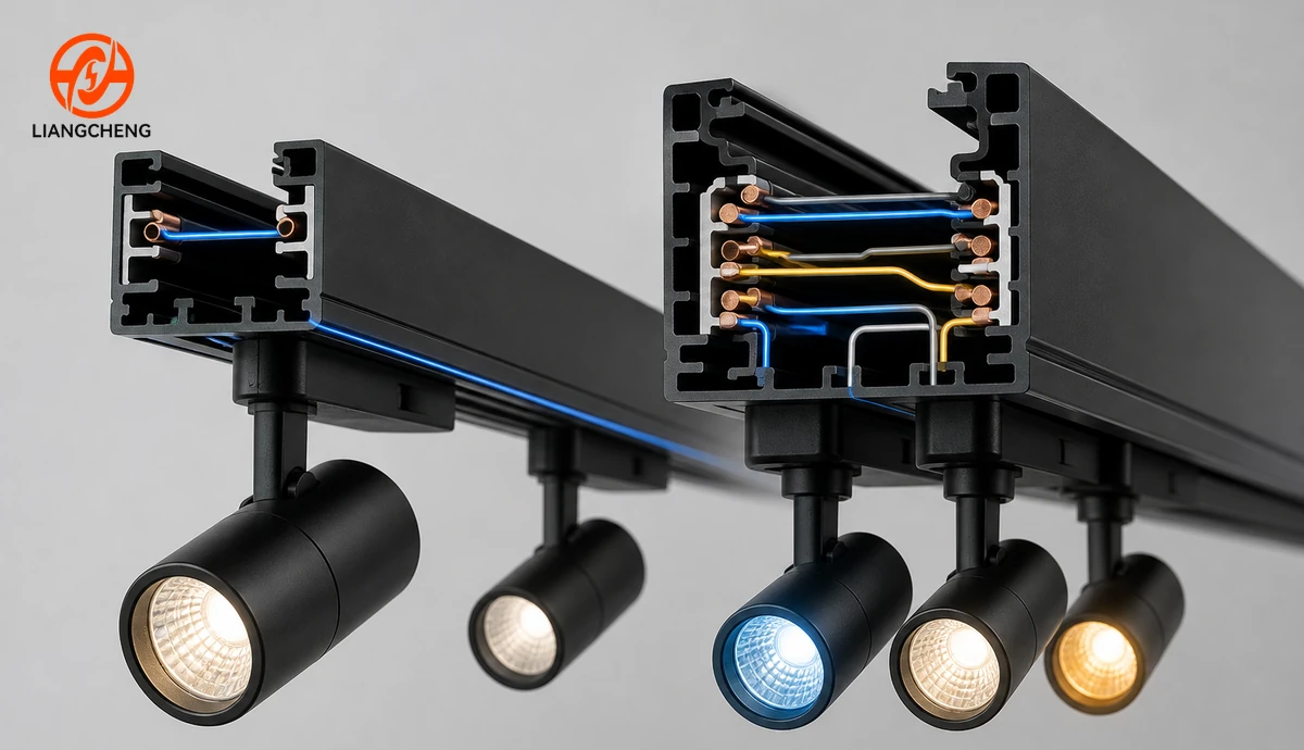
Consider a retail rail above one long wall. Group one can serve window-facing accent lights. Group two can serve wall-wash fixtures. Group three can serve general display lighting. The store can operate a daytime scene, an evening window scene, or a maintenance scene without installing three parallel rails.
Multi-circuit does not automatically mean that every fixture has individual digital control. A circuit group may still contain several fixtures that respond together. Individual addressing requires a compatible control architecture, suitable luminaires or adapters, and the required control wiring or communication method. The terms must not be treated as synonyms.
Why circuit count and wire count are not the same question
Commercial product names often use wire, line, phase, channel, or circuit in ways that vary across markets and manufacturers. A buyer should not infer the number of independently controlled groups only from the number in a product name.
An electrical circuit needs a defined current path and protective arrangement. Conductors within a track may serve line connections, a shared neutral, protective earth, control functions, or other documented purposes. The exact allocation depends on the product family and applicable design.
Use three separate questions:
- How many conductive paths are physically present?
- What function does each conductive path perform?
- How many independent control groups does the complete system support?
The model wiring diagram, rail cross-section, feed terminal schedule, adapter documentation, and test information should answer all three. The overview of 2-wire, 3-wire, and 4-wire track rail types explains why names alone are not enough. The separate 6-wire track rail guide applies the same principle to higher-conductor systems.
How control grouping changes a lighting scene
Control groups should follow visual tasks, not arbitrary fixture counts. Begin by listing which lights must respond together during each operating mode.

A useful scene schedule might contain:
- Opening scene: general and feature lighting at the level required for customer preparation.
- Trading scene: display groups balanced for normal customer hours.
- Promotion scene: feature and window groups emphasized while background groups are reduced.
- Evening scene: window or facade-facing groups remain active after the main space closes.
- Cleaning scene: broader illumination supports staff tasks.
- Energy-saving scene: selected zones operate according to occupancy or schedule.
A single-circuit design can still be suitable when all of these scenes use the same fixtures together. A multi-circuit design becomes valuable when the scene table repeatedly asks one group to behave differently from another group on the same rail route.
Does multi-circuit always provide better lighting?
No. Circuit count does not determine beam quality, color rendering, glare, aiming, illuminance, or visual comfort. Those results depend largely on the selected track lights, optics, layout, aiming, surface properties, and commissioning.
Multi-circuit control improves operational flexibility. It does not correct poor photometric design. A project can have several circuits and still produce uneven lighting, excessive glare, weak vertical illumination, or wasted energy. A simple single-circuit layout with well-selected fixtures may perform better than an unnecessarily complex system.
The relationship between the support system and the luminaire is explained in track rail vs track light. The rail supplies the route and control architecture; the track light produces and directs the illumination.
How should circuit loads be planned?
Every circuit and component has electrical limits. The designer must calculate connected load, consider driver behavior, select suitable protective and switching devices, and remain within the ratings of the rail, feeds, connectors, adapters, controls, and luminaires.
Use a circuit schedule with at least these fields:
| Schedule field | Purpose |
|---|---|
| Circuit or group identifier | Links the distribution, control, adapter assignment, and drawing |
| Rail run and feed point | Defines where the group enters the track system |
| Fixture model and quantity | Establishes compatibility and connected equipment |
| Rated input per fixture | Supports load calculation |
| Total connected load | Checks the group against component and design limits |
| Switching or dimming device | Defines how the group is operated |
| Scene membership | Shows which operating modes use the group |
| Adapter selection setting | Supports installation and commissioning |
Do not move fixtures between groups or add fixtures without updating the load schedule. LED drivers can also create inrush and control compatibility considerations that are not visible from steady-state wattage alone. A qualified electrical professional should complete the design, installation, testing, and code review for the project location.
How does dimming fit into single-circuit and multi-circuit systems?
Dimming and circuit count are separate design decisions. A single circuit can be dimmable when all connected drivers, the dimming method, the control device, and the electrical design are compatible. Each circuit in a multi-circuit system can also be switched or dimmed according to its own control path.
Before specifying dimming, confirm:
- the dimming protocol or method;
- driver compatibility and minimum load behavior;
- dimming range and low-end stability;
- control conductor or communication requirements;
- device capacity and driver inrush;
- flicker requirements;
- failure behavior and manual override;
- commissioning responsibility.
A multi-circuit rail does not make a non-dimmable fixture dimmable. It only provides the electrical paths supported by the documented system.
Which system is easier to install?
A single-circuit system usually has fewer terminals, fewer control groups, and a simpler commissioning sequence. That can reduce design time and the chance of assignment errors. It may also require less distribution and switching equipment.
A multi-circuit system requires more coordination. Feed orientation, circuit continuity through connectors, adapter group selection, control outputs, load schedules, and labeling all need careful attention. However, it can simplify the visible ceiling layout by replacing several parallel single-circuit rails with one coordinated multi-circuit route.
Installation complexity should therefore be evaluated at the system level:
- number of rail runs;
- number and location of feeds;
- distribution and control equipment;
- ceiling access;
- connector geometry;
- fixture assignment;
- testing and documentation effort;
- future changes expected during operation.
When is single-circuit track the better choice?
Choose a single-circuit system when the project has one clear control zone and no realistic need to separate fixtures on the same rail. Suitable cases may include:
- a compact residential accent run;
- a small gallery wall that operates as one group;
- a single restaurant feature area;
- a short display rail with one schedule;
- a straightforward replacement where the existing distribution supports one circuit;
- a cost-sensitive project where additional groups offer no operational benefit.
The strongest reason to choose single-circuit is not low price alone. It is a stable requirement that genuinely needs one group.
When is multi-circuit track the better choice?
Choose multi-circuit when several lighting tasks share the same rail route but need different operating behavior. Typical cases may include:
- retail walls with separate merchandise and ambient layers;
- showrooms with changing product priorities;
- museum or gallery layouts with several exhibition zones;
- hospitality spaces that change from daytime to evening scenes;
- large commercial floors with scheduled areas;
- window displays that must remain active after other fixtures switch off;
- multi-use interiors where fixture assignments change frequently.
The article on commercial track rail system design explains how flexible rail layouts support layered lighting and future merchandising changes.
How should a renovation be evaluated?
Existing buildings require a condition and compatibility audit before a circuit decision. Identify the installed rail family, conductor arrangement, feeds, connectors, controls, protection, mounting condition, and available supply paths. Check whether documentation and spare components remain available.
Ask these questions:
- Does the existing rail support more than one documented circuit?
- Are separate supply and control paths already present?
- Can the existing connectors preserve all required circuit paths?
- Are the existing fixtures and adapters compatible with the proposed system?
- Can the distribution equipment support the revised loads and controls?
- Will ceiling access permit new feeds or replacement rails?
- Does the condition of the existing rail justify reuse?
A rail that appears to have multiple conductors may not provide the desired control groups. A rail that physically accepts an adapter may still be electrically incompatible. For 3-wire projects, use the guide to track light compatibility with 3-wire rails as part of the audit.
What belongs in the bill of materials?
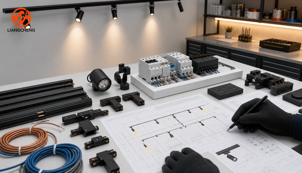
Price and order the complete system, not only the rail and lights. A coordinated bill of materials may include:
- rail sections with exact profile, length, finish, and mounting type;
- power feeds for the required circuit architecture;
- straight, corner, T, cross, or flexible connectors where required;
- end caps and mechanical mounting parts;
- suspension components or recessed trims;
- track lights with compatible adapters;
- adapter selectors or settings documented by group;
- switching, dimming, or control devices;
- distribution and protective equipment;
- labels, drawings, test records, and spare parts.
Use one approved system family whenever possible. Similar color and dimensions do not prove that a feed, connector, or adapter is compatible. The aluminum track rail buying guide provides additional purchasing criteria.
How should multi-circuit compatibility be verified?
Compatibility has mechanical, electrical, control, and documentation layers. Confirm all of them before ordering.
| Compatibility layer | Verification |
|---|---|
| Mechanical | Profile dimensions, keying, insertion direction, locking geometry, and load support |
| Electrical | Contact position, conductor function, polarity, voltage, current, earthing, and insulation |
| Circuit selection | Adapter selection range, setting method, and group mapping |
| Control | Switching device, dimming method, driver behavior, and scene command |
| Acessórios | Feed and connector continuity through every route and corner |
| Documentation | Model references, diagrams, ratings, installation instructions, and approval records |
Request samples of the actual rail, feed, connectors, and fixture adapters when an importer or project team needs to qualify a new system. Test assembly and circuit assignment before a large order.
How should the system be commissioned?
Commissioning proves that the installed system matches the design. The exact test procedure must follow product instructions and local requirements, but the project record should normally confirm:
- rail and connector installation condition;
- feed orientation and terminal allocation;
- protective continuity and required electrical tests;
- correct circuit identification;
- adapter assignment for every fixture;
- connected load by group;
- switching and dimming response;
- scene operation and manual override;
- fixture aiming and final visual result;
- updated drawings and circuit schedule.
Test one group at a time before testing combined scenes. Incorrect adapter settings can be difficult to notice when several circuits operate simultaneously.
What are the cost differences?
Single-circuit systems often have lower initial cost because the rail, feeds, controls, documentation, and commissioning can be simpler. Multi-circuit systems may require more complex rail construction, adapters, feeds, distribution, switching, and labor.
Initial price is not the only cost. A multi-circuit system may reduce the number of visible rail runs, support future scene changes, reduce ceiling alteration during merchandising updates, or lower operating hours for selected groups. A single-circuit system may remain the better lifecycle choice when the space has one stable function.
Compare:
- complete installed material cost;
- design and commissioning time;
- ceiling coordination and access;
- control equipment;
- expected future layout changes;
- energy schedules by zone;
- spare parts and replacement compatibility;
- training and documentation.
A project decision framework
- List visual tasks. Identify display, wall-wash, accent, general, cleaning, and after-hours needs.
- Create a scene table. Show which fixture groups operate in every scene.
- Map groups to rail routes. Check where different groups share one physical route.
- Choose the minimum useful circuit count. Add complexity only where the scene table requires it.
- Select one documented system family. Match rail, feeds, connectors, adapters, lights, and controls.
- Calculate loads and control capacity. Check all component ratings and operating behavior.
- Review installation and retrofit constraints. Confirm ceiling access, supply paths, and mounting.
- Approve samples and mock-ups. Verify compatibility and visual performance.
- Commission and document. Test every group and update the final circuit schedule.
This process selects the circuit architecture from real operating needs rather than from a product label.
How much future capacity should a project include?
Future-ready design does not mean selecting the highest circuit count available. It means identifying changes that are reasonably likely during the planned life of the space and reserving only the capacity that supports those changes.
A retail tenant may expect seasonal display zones to move along one wall. A gallery may need to divide one long route into changing exhibition groups. A hospitality project may expect new daytime and evening scenes. These cases can justify spare circuit or control capacity. A small fixed display that has used one operating schedule for many years may not benefit from the same investment.
Record future assumptions in the design brief:
- which zones may change;
- how often fixtures may be moved;
- whether new fixture types are expected;
- whether control scenes may expand;
- which spare parts must remain available;
- which circuit and load capacity is intentionally reserved.
Unused capacity still has a cost in rail, feeds, controls, installation, documentation, and commissioning. Compare that cost with the disruption of future alteration. The existing comparison of 2-wire and 3-circuit track rail provides a product-level view; the scene schedule in this guide provides the project-level reason for selecting either architecture.
Future capacity should also remain usable. Preserve final drawings, model numbers, adapter settings, circuit schedules, approved fixture lists, and spare component requirements. Capacity that cannot be identified or supported later has little practical value.
Common misconceptions
More conductors always mean more independent circuits
Not necessarily. Conductor functions vary. Confirm the terminal schedule and supported control groups for the exact system.
Multi-circuit means every light is individually controlled
No. Several lights assigned to one circuit still respond as a group. Individual control requires a compatible addressing and communication architecture.
A multi-circuit rail saves energy automatically
No. It creates the opportunity to switch or dim groups separately. Energy results depend on schedules, controls, commissioning, and user behavior.
A single-circuit system is only for homes
No. Many commercial areas need one stable lighting group and can use single-circuit track effectively.
A multi-circuit system is always the premium choice
No. The best system is the least complex architecture that fully supports the required scenes, loads, compatibility, and future plans.
Frequently asked questions
Can single-circuit track lights be used on multi-circuit rail?
Only when the adapter and fixture are explicitly documented as mechanically and electrically compatible with the rail and its selection method. Similar appearance is not enough.
Can fixtures change groups after installation?
Many multi-circuit systems allow a compatible adapter to be reassigned, but the method is product-specific. Isolate power and follow the instructions. Update the circuit schedule after the change.
Can one multi-circuit rail use spotlights, pendants, and linear fixtures?
It can when every fixture uses an approved compatible adapter and remains within mechanical, electrical, and control limits.
Is a separate neutral needed for every circuit?
Conductor allocation varies by system and electrical design. Do not assume a shared or separate arrangement. Use the exact wiring diagram and professional design for the project.
Can a single-circuit installation be upgraded later?
Sometimes, but the answer depends on the existing rail, conductors, feeds, distribution, controls, ceiling access, and fixture adapters. A complete audit is required.
How many circuits should a retail store use?
Use the minimum number that supports the scene schedule and operational zones. Window, wall display, feature, and general groups are common planning categories, but the final count should follow the actual layout.
Final answer
Single-circuit track lighting operates compatible fixtures as one electrical group. Multi-circuit track lighting allows fixtures on one coordinated rail route to be assigned to several separately controlled groups. Choose single-circuit for one stable scene and multi-circuit when distinct zones, schedules, or lighting layers must share the same route. Verify conductor functions, adapters, feeds, connectors, loads, controls, and commissioning requirements for the exact product family before installation.
Precisa de Soluções Personalizadas de Iluminação de Trilhos?
Entre em contato com a Liangcheng Lighting para soluções de trilhos de alumínio OEM/ODM e suporte profissional de iluminação.
Relacionado