







Lesezeit: 13 Minuten
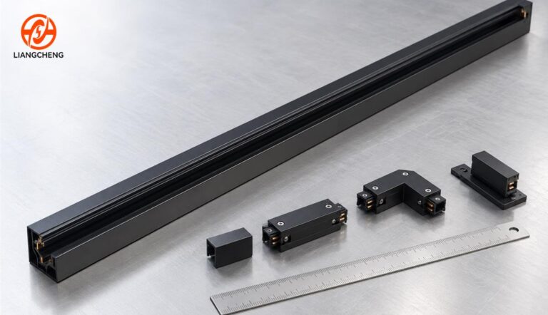
Short answer: track lighting rail dimensions are not defined by one universal size. A complete size specification normally includes the rail section length, external profile width and height, internal channel geometry, mounting or cutout dimensions, connector allowances, adapter clearance, and manufacturing tolerances. Common stock lengths include 1 m, 1.5 m, 2 m, and 3 m, but cross-sections vary by system family and manufacturer. Two rails with the same nominal width can still be incompatible.
The most reliable buying rule is simple: never order track rail from length and width alone. Match the rail, feed, connectors, end caps, adapters, circuit arrangement, electrical ratings, and mounting accessories as one tested system. For existing installations, use a dimensioned cross-section drawing or an approved physical sample rather than a visual guess.
This guide focuses on how to measure and document track lighting rail dimensions for design, renovation, installation coordination, and wholesale purchasing. It does not repeat the general product selection covered in the Kaufberatung für Schienenbeleuchtungsprofile aus Aluminium.
Track lighting rail dimensions at a glance
| Dimension | What it measures | Why it matters | Common error |
|---|---|---|---|
| Section length | End-to-end length of one rail piece | Layout, joints, freight, and cutting plan | Treating section length as finished run length |
| Body width | Outer aluminum width excluding flanges | Visual scale, clips, and ceiling coordination | Confusing body width with recessed cutout |
| Overall width | Maximum width including flanges or trim | Finished appearance and coverage | Using it as the opening size |
| Profilhöhe | Outer depth of the aluminum body | Projection or recess depth | Ignoring feeds and connectors above the rail |
| Cutout width | Required ceiling opening for recessed track | Accurate fit and flange coverage | Copying the rail body width without tolerance |
| Channel opening | Usable opening where the adapter enters | Mechanical adapter compatibility | Assuming equal openings mean equal systems |
| Conductor position | Location and spacing of electrical contacts | Electrical compatibility and circuit selection | Checking only the number of contacts |
| Connector allowance | Length added, removed, or overlapped at a joint | Finished run and corner accuracy | Adding catalog rail lengths without an assembly drawing |
| Adapter envelope | Maximum adapter width, height, and insertion depth | Clearance and locking security | Measuring only the visible fixture body |
| Tolerance | Allowed variation from the nominal drawing | Fit, alignment, and batch consistency | Specifying nominal values with no permitted range |
The table shows why a useful size guide must go beyond a single catalog number. Every dimension belongs to a different design decision, and several dimensions interact when the system is assembled.
Are track lighting rails a standard size?
Track rail lengths are often standardized within a supplier catalog, but track rail cross-sections are not globally interchangeable. Conventional mains-voltage track, multi-circuit track, low-voltage magnetic track, recessed track, and custom architectural profiles use different mechanical and electrical architectures.
Names such as slim, mini, standard, commercial, 20 mm, or three-circuit may describe a product family, but they do not prove compatibility. A nominal width can refer to the outer body, visible face, internal channel, or recessed opening. Regional track families can also use different contact layouts and mechanical keys even when the outside measurements look similar.
This distinction is especially important when replacing an existing system. The comparison of H-Type, J-Type, and L-Type track lighting explains why profile appearance and contact count alone cannot identify an adapter family.
What are common track rail lengths?
Common stock section lengths include 1 m, 1.5 m, 2 m, and 3 m. Availability varies by product family, finish, market, packaging method, and transport limits. Shorter sections are easier to ship and handle, while longer sections reduce the number of visible joints in a straight run.
Length selection should balance four practical issues:
- Layout: the section pattern should place joints away from critical visual areas where practical.
- Transport: long aluminum profiles require stronger packaging and more careful handling.
- Site access: elevators, corridors, stair turns, doorways, and ceiling obstructions can limit usable section length.
- Installation: a longer piece reduces joints but can be harder to align overhead.
A project should not simply divide the room length by a stock rail length. Straight connectors, corner connectors, power feeds, end caps, expansion strategy where relevant, and required wall clearances can change the assembled dimension.
How do you calculate the finished track run length?
The finished run should be calculated from an assembled system drawing, not from rail sections in isolation. A useful planning equation is:
Finished run length = installed rail section lengths plus exposed connector additions minus inserted overlaps, adjusted for end components and required clearances.
Some straight joiners fit almost entirely inside adjacent rails. Other feeds and connectors occupy visible length. An L connector may define the centerline turn while also changing the outside corner envelope. A suspended feed canopy can require additional ceiling space without changing the rail centerline length. Manufacturer drawings should state which reference points control each dimension.
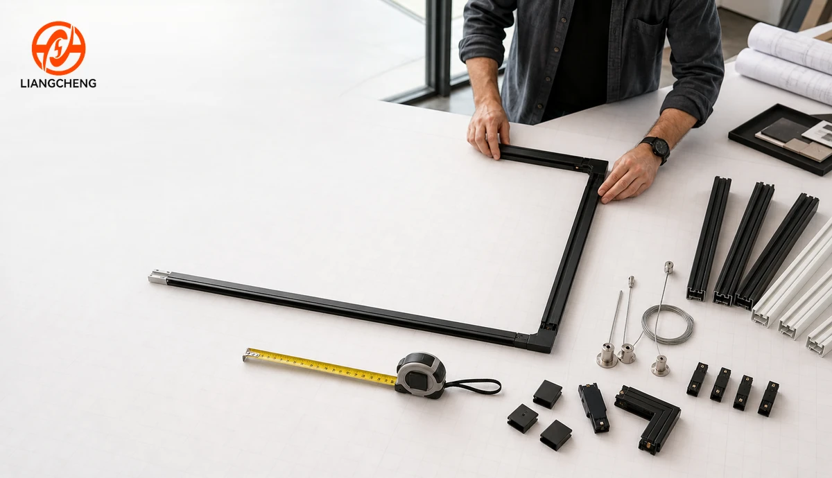
For a rectangular or L-shaped layout, mark a centerline and dimension every straight segment between defined corner reference points. Then add a component schedule showing each feed, joiner, corner, end cap, suspension point, and cut piece. This approach prevents a common site problem: the total linear meters are correct, but the assembled geometry does not fit the ceiling.
Which cross-section dimensions matter?
A cross-section drawing is the most useful document for identifying a rail. It should show more than the outer rectangle. The drawing should include body width, overall width, profile height, channel opening, internal depth, flange projection, wall thickness where specified, insulation geometry, conductor positions, locking features, and relevant mounting grooves.
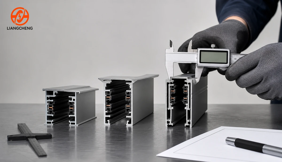
Some catalogs contain narrow profiles in the approximate 15 to 20 mm range and larger commercial profiles around 25 to 35 mm. Magnetic track catalogs may also list nominal widths such as 20 mm, 25 mm, 26 mm, or 35 mm. These figures are planning examples, not universal compatibility codes. The same nominal width can describe different reference points, voltage classes, conductor layouts, fixture families, and installation methods.
When requesting a quotation, attach a labeled cross-section drawing. If the project must match an existing rail, also send clear photographs, the original model reference if available, and a physical cut sample. Do not rely on a tape measure photograph alone because perspective and rounded edges can hide small but critical differences.
How do surface, recessed, and suspended dimensions differ?
Surface-mounted track
For surface-mounted track, record the external body width and height, mounting-hole or clip spacing, fastener zone, feed envelope, connector envelope, and distance from the mounting plane to the adapter or fixture pivot. The visible height affects the ceiling appearance, while the internal geometry controls compatibility.
The mounting detail should also show the base condition. A rail fixed to concrete, gypsum board with structure above, wood, or a metal channel may use different anchors and support spacing. Rail dimensions alone do not determine safe support spacing; the rail load rating, fixture weight, layout, substrate, and local requirements must be considered by qualified project professionals.
Recessed track
For recessed track, separate the body width from the flange width and cutout width. The body passes into the ceiling opening. The flange covers the edge of the opening. The cutout must allow installation while leaving enough coverage for a clean finish. Also record profile depth, ceiling board thickness range, clip or bracket envelope, and required void clearance.
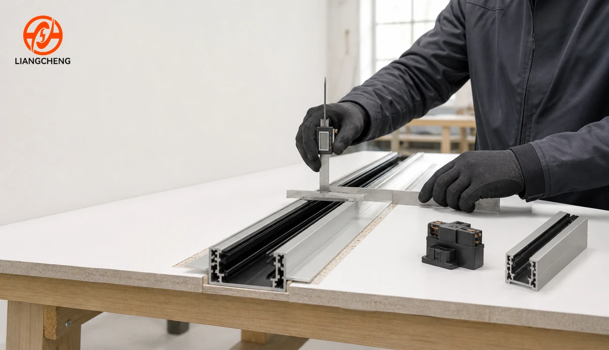
Trimless recessed profiles need even closer coordination because the finishing material may meet the rail edge directly. The specification should show plaster or board buildup, fixing flange geometry, finished opening, protective masking area, and access requirements for feeds and connectors.
Suspended track
For suspended track, add suspension drop, cable or rod length, suspension center spacing, canopy diameter, power-cable route, rail centerline, and finished height above the floor. The cross-section must provide the required stiffness for the selected spacing and fixture load. Suspension components should belong to the approved rail family.
Designers should dimension both the ceiling anchor points and the finished rail plane. A correct rail length can still produce a poor result if suspension points conflict with building services or if the rail hangs at an inconsistent level.
How do conventional and magnetic track sizes compare?
Conventional track and magnetic track should be treated as different system architectures. Conventional track often uses a mains-voltage adapter that twists or locks into a keyed channel. Magnetic track commonly uses a dedicated low-voltage module interface, magnetic retention, and a system-specific contact arrangement. Width alone cannot bridge these differences.
A slim magnetic rail may appear visually smaller than a conventional commercial rail, but the complete installation can require a driver location, deeper recessed body, special feed, or larger connector envelope. The relevant comparison therefore includes the visible face, concealed body, power equipment, fixture module, and service access.
The guide to ordinary track lights versus magnetic track lights covers the wider differences in attachment, electrical architecture, flexibility, and installation.
Why adapter dimensions are as important as rail dimensions
A rail is useful only when the intended adapter can enter, contact, lock, and carry the fixture securely. An adapter check should include insertion width, insertion depth, key orientation, contact position, locking-tab envelope, selector position where used, visible adapter height, and rotation clearance.
Fixture spacing must use the adapter envelope rather than the narrowest part of the fixture body. Two spotlights may need extra center-to-center distance so their adapters can be locked, aimed, and removed. Pendants and linear luminaires can create different load and clearance demands. The article on track rail versus track light explains how the two components form one coordinated system.
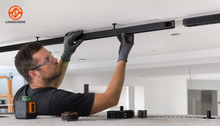
For retrofit work, test the exact adapter in the existing rail across several positions. Wear, deformation, paint buildup, previous repairs, and manufacturing variation can affect the fit. Electrical verification and any installation work should be completed by qualified personnel under applicable requirements.
Do conductor count and circuit count change profile size?
Additional conductors or control paths can require more internal space, but conductor count does not translate into one predictable outer dimension. Manufacturers can arrange insulation, copper conductors, earthing features, and mechanical keys differently. A larger rail is not automatically multi-circuit, and a compact rail is not automatically single-circuit.
Specify circuit function separately from profile size. The electrical schedule should state the number of independently controlled groups, conductor functions, voltage, current rating, earthing arrangement, control method, and matching adapter. For control planning, see the comparison of single-circuit and multi-circuit track lighting.
What tolerances should a track rail drawing include?
A nominal dimension without tolerance is incomplete. Aluminum extrusion, cutting, machining, insulation placement, conductor assembly, and coating all introduce controlled variation. The necessary tolerance depends on the dimension function, production process, finish, length, and system design.
At minimum, request or define tolerances for:
- Cut section length and squareness.
- External width and height.
- Channel opening and internal key dimensions.
- Flange width and straightness.
- Wall thickness where it is a controlled requirement.
- Conductor and insulation position.
- Mounting-hole or clip location.
- Twist, bow, and straightness over the section length.
- Finish thickness where it can affect fit.
Do not invent a very tight tolerance simply to make a drawing look precise. Unnecessarily tight values can increase cost without improving the installed result. The manufacturer and project engineer should agree on functional limits and a measurement method.
How should an existing track rail be measured?
Disconnect and verify electrical safety before inspection. Where direct electrical or mechanical work is required, use qualified personnel. Then follow a controlled identification process:
- Record the installation: photograph the rail, feed, connectors, end caps, adapter, labels, and mounting condition.
- Identify the system reference: look for a model, drawing, purchase record, or approved supplier statement.
- Measure a clean cross-section: use a proper sample when possible. Record body width, overall width, height, opening, internal depth, and flange geometry.
- Map contacts and keys: record position and function, not only quantity.
- Measure the adapter: document the insertion body, contacts, locking features, and operating clearance.
- Check components: measure feeds, straight joiners, corners, suspension parts, and end caps.
- Build a trial assembly: confirm mechanical fit, alignment, locking, circuit behavior, and continuity under an approved test plan.
A caliper is appropriate for cross-section details, while a steel rule or verified tape is better for longer sections. Measure at more than one point to detect taper, bow, damage, or coating buildup. Record units and measurement conditions on the same sheet.
How do rail dimensions affect project layout?
Profile size affects both appearance and coordination. A narrow visible face may suit a low ceiling or minimal interior. A deeper or wider commercial profile may provide the internal space, stiffness, and accessory family required by the project. The decision should follow the complete system specification rather than appearance alone.
Important layout consequences include:
- Distance from the wall to the rail centerline.
- Fixture aiming space and visual cutoff.
- Clearance from sprinklers, detectors, diffusers, beams, and access panels.
- Recess depth and conflict with ceiling services.
- Corner radius or connector envelope.
- Joint visibility and alignment over long runs.
- Suspension position and finished mounting height.
- Access to feeds, drivers, and service components.
Commercial projects should coordinate rail centerlines with the lighting plan, ceiling plan, reflected ceiling services, structural supports, and fixture aiming study. The guide on commercial LED track rail system design explains how this coordination supports adaptable lighting layouts.
How should rail quantity be calculated?
Start with dimensioned centerline runs, then break each run into available stock or custom-cut sections. Add every straight connector, directional connector, feed, end cap, suspension set, mounting clip, and approved spare. Keep rail length and accessory quantity as separate schedules.
For wholesale or multi-site projects, include a cutting and packing plan. A small allowance can cover approved site cuts and damage, but excess should be based on project risk rather than an arbitrary percentage. Custom-cut rails can reduce waste and joints, while stock lengths can simplify replacement and inventory.
Long rails need packaging that controls bending, twist, surface abrasion, and end damage. Confirm carton length, pieces per carton, protective separators, end reinforcement, pallet arrangement, gross weight, and handling limits. The wholesale aluminum track rail sourcing guide provides wider purchasing and packaging considerations.
What belongs in a track rail dimension specification?
A purchase specification should include a drawing and a component matrix. Use the following checklist:
- System family and exact rail model.
- Installation method: surface, recessed, trimless, or suspended.
- Section lengths and permitted cut-length tolerance.
- Body width, overall width, height, and channel opening.
- Recessed cutout, flange, board-thickness range, and void clearance.
- Cross-section drawing with internal keys, insulation, and conductor positions.
- Wall thickness and alloy when these are controlled requirements.
- Circuit arrangement, voltage, rated current, earthing, and control method.
- Approved adapters and luminaires.
- Feed, connector, end-cap, mounting, and suspension dimensions.
- Finish, color reference, gloss range, and protected surfaces.
- Straightness, bow, twist, cut quality, and visual acceptance criteria.
- Sample approval, inspection method, packaging, and labeling.
Custom profiles should also define drawing revision, tooling ownership where relevant, golden sample, change-notice process, and reapproval conditions. More options for project-specific length, cross-section, finish, and mounting are covered in the guide to custom LED track rail solutions.
Common track rail sizing mistakes
- Ordering by nominal width: the reference point may differ between catalogs.
- Ignoring the cross-section: outer dimensions do not show internal keys and conductor locations.
- Using section length as run length: connectors and end components can change the assembly.
- Confusing body width with cutout width: recessed rails need separate body, flange, and opening dimensions.
- Measuring only the rail: adapters, feeds, corners, drivers, and suspension parts also need clearance.
- Assuming similar profiles are compatible: mechanical fit does not prove electrical compatibility.
- Leaving tolerances undefined: nominal dimensions cannot control batch fit by themselves.
- Skipping a trial assembly: drawings should be confirmed with the complete approved component family.
- Forgetting logistics: a section that fits the ceiling may not fit the route into the building.
Frequently asked questions
What is the standard length of a track lighting rail?
Common catalog lengths include 1 m, 1.5 m, 2 m, and 3 m, but availability varies. Custom cutting may also be possible. Confirm the actual cut-length tolerance, connector allowance, packaging, and assembled run length.
What is the standard width of track lighting rail?
There is no single universal width. Some catalogs use narrow profiles around 15 to 20 mm, while larger profiles may be around 25 to 35 mm. Magnetic systems also use several nominal widths. These figures do not prove compatibility; use the exact cross-section and system reference.
Does a wider track rail carry more weight?
Not necessarily. Load capacity depends on aluminum geometry, wall thickness, alloy and temper, mounting or suspension spacing, connectors, fasteners, substrate, and fixture load. Use the tested load data and approved installation detail for the exact system.
Is recessed cutout width the same as rail width?
Usually not. The rail body, visible flange, and ceiling cutout are separate dimensions. A trimless system can add another finishing geometry. Use the manufacturer drawing for the complete ceiling detail.
Can a track rail be cut to size on site?
Some rail systems permit approved site cutting, but the method, cut position, conductor treatment, insulation, deburring, end protection, and reassembly requirements vary. Follow the system instructions and applicable electrical requirements.
Can two rails with the same dimensions use the same track heads?
No assumption should be made. Mechanical keys, contact position, polarity, circuit selection, ratings, and locking features can differ. Confirm an approved rail-and-adapter combination.
Which dimension is most important for a replacement rail?
No single dimension is sufficient. The exact system identity, cross-section, contact and key layout, adapter fit, electrical ratings, and connector family must all match. A physical sample and approved compatibility statement provide stronger evidence than a width measurement.
Final answer
A complete track lighting rail size is a coordinated set of dimensions. Record section length, body and overall width, profile height, channel geometry, recessed cutout or mounting detail, connector allowances, adapter envelope, conductor position, and tolerances. Use common lengths such as 1 m, 1.5 m, 2 m, and 3 m only as planning references.
The correct rail is not the one with the closest outside measurement. It is the rail whose dimensioned profile, accessories, adapters, electrical configuration, mounting system, and project clearances have been verified together. A cross-section drawing, component schedule, approved sample, and trial assembly turn a generic size request into a reliable procurement specification.
Benötigen Sie individuelle Schienensystemlösungen?
Kontaktieren Sie Liangcheng Lighting für OEM/ODM Aluminium-Schienenlösungen und professionelle Beleuchtungsunterstützung.
Bezogen