







Quick answer: A surface-mounted track lighting rail is installed in ten steps: confirm the rail system and the layout, isolate and test the power supply, mark a straight centerline on the ceiling, choose fixings for the ceiling material, prepare the electrical feed, cut and deburr the rail if needed, wire the live end feed to the correct conductors, fix the rail at the specified support spacing, join runs with matching connectors and fit end caps, then install the track heads and test the circuit before handover. The two steps that cause most failures are wiring the feed to the wrong conductor or circuit, and mixing rails, connectors and adapters from different systems. A qualified electrician should make the mains connection, and all work must follow local electrical codes.
How this guide differs from a mounting comparison: choosing between surface, recessed and suspended mounting is covered in surface-mounted vs recessed vs suspended track rail installation. This article starts after that decision and explains the actual installation of a surface-mounted rail, including wiring for 2-wire, 3-wire, 4-wire and 6-wire systems, compatibility checks, common specifications, project applications and what buyers should check before ordering rails for installation teams.
What is a surface-mounted track lighting rail?
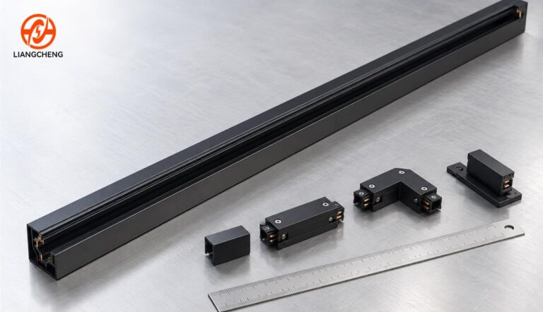
A surface-mounted track lighting rail is an aluminum profile with insulated copper conductors that is fixed directly onto the face of a ceiling or wall, so the whole rail remains visible below the surface. Track lights, pendants or linear fixtures attach to the rail through adapters that click into the profile and take power from the conductors, so fixtures can be moved, added or re-aimed without new wiring. Surface mounting requires no ceiling cutout, which makes it the fastest and most flexible method for retail stores, galleries, offices, showrooms, restaurants and residential projects.
The main difference between surface-mounted rails and other mounting types is the ceiling interface. A recessed rail sits in a cutout so its face is flush with the ceiling, and a suspended rail hangs from wire or rod suspension kits. A surface-mounted rail only needs a flat, structurally sound ceiling and a power feed point, which is why it is the most common choice for refurbishments and for projects where the lighting layout may change.
What tools and materials are needed to install a surface-mounted track rail?
Installing a surface-mounted track rail requires standard electrical and drilling tools plus a complete, matching set of track components. The tools are a voltage tester, a laser level or chalk line, a tape measure, a pencil, a drill with bits for the ceiling material, screwdrivers, wire strippers, a fine-tooth hacksaw or miter saw with an aluminum blade, a deburring tool or file, a stable ladder or platform, and an insulation resistance tester for commercial projects.
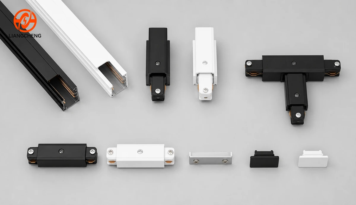
The materials are the rail sections, a live end feed or middle feed connector, straight joiners, any corner, T or cross connectors, end caps, mounting clips or screws supplied for the rail, fixings suited to the ceiling (wood screws, toggle anchors, hollow-wall anchors or concrete anchors), the power cable, and the track heads with matching adapters. Before installation starts, every component should be checked against the rail’s system type, because a feed or joiner from a different system may not fit or may connect the wrong conductors. A complete list of rail accessories is explained in the track lighting rail accessories system guide.
Step 1: How should the rail system and layout be confirmed before installation?
The rail system and layout should be confirmed by checking the lighting drawing, the rail type and the circuit plan before any hole is drilled. The installer needs to know the rail’s system type, such as 2-wire single circuit, 3-wire with earth, 4-wire three-circuit or 6-wire multi-circuit, plus the run lengths, the position of the feed point, the location of corners and branches, and which fixtures go on which circuit. These decisions determine which connectors and feeds are needed and where the power cable must arrive.
The layout should also be checked against the site. Ceiling joists, sprinklers, HVAC diffusers, smoke detectors and existing light points can block the planned line. Moving the rail by a short distance during layout costs nothing, while moving it after drilling leaves visible holes. On larger projects, a short mock-up section installed in a representative area confirms appearance, fixings and adapter fit before the full installation begins.
Step 2: How should the power supply be isolated before installing a track rail?
The power supply should be isolated by switching off the relevant circuit breaker, locking or tagging it so it cannot be switched back on, and testing the conductors at the feed point with a proven voltage tester. Switching off a wall switch is not enough, because the supply cable may still be live on one conductor. On multi-circuit rails, every circuit that feeds the rail must be isolated and tested, since one rail may be supplied from two or three different breakers.
Testing should follow the prove-test-prove method: check the tester on a known live source, test the conductors, then check the tester again. This simple routine prevents the most serious installation accident, which is working on a cable that was assumed to be dead.
Step 3: How do you mark a straight line for a surface-mounted track rail?
A straight line for a surface-mounted track rail is marked with a laser level or a chalk line between two measured reference points. Measure the distance from a wall or other fixed reference at both ends of the planned run, mark the points, and project or snap a line between them. For long runs, check the line at intermediate points, because walls in many buildings are not perfectly parallel and a rail aligned to one wall can look crooked against another.
The rail position should also respect lighting geometry. In retail and gallery projects, track rails for accent lighting are often placed so that the aiming angle to the display or wall is around 30 degrees from vertical, which reduces glare and reflections. Marking the feed point, joiner positions, corners and fixing points on the line at this stage makes the next steps faster and avoids drilling into joints.
Step 4: Which fixings should be used for different ceiling types?
The fixings for a surface-mounted track rail should be chosen according to the ceiling material and the total load of the rail and fixtures. The table below shows typical choices.
| Ceiling type | Recommended fixing | Notes |
|---|---|---|
| Concrete slab | Concrete or expansion anchors with screws | Use a hammer drill; check for embedded services before drilling |
| Timber joists or battens | Wood screws into the framing | Strongest option when the rail line crosses the framing |
| Plasterboard / gypsum board | Toggle bolts or metal hollow-wall anchors | Avoid plastic plugs alone for heavy fixtures |
| Metal suspended ceiling grid | Fixings into a secondary support channel | Ceiling tiles cannot carry rail loads by themselves |
| Timber or panel ceiling | Wood screws of suitable length | Check panel thickness and backing |
Fixing spacing should follow the rail manufacturer’s instructions. As a common practice, surface-mounted rails are fixed at intervals of roughly one meter or less, with a fixing close to each end and on both sides of every joiner. Heavier fixtures, pendants or high fixture densities need closer spacing. The fixings must hold the rail straight and tight against the ceiling so that the profile does not twist when adapters are inserted.
Step 5: How should the electrical feed be prepared?
The electrical feed should be prepared by bringing the supply cable to the planned feed position, usually at one end of the rail for a live end feed or at a point along the run for a middle feed, and leaving enough cable length to make the connection comfortably. The cable should arrive through a junction box or a ceiling outlet that meets local code, and its conductors must match the rail system: line, neutral and protective earth for single-circuit rails, or several lines plus neutral and earth for multi-circuit rails.
Where the feed is not directly above the rail end, a feed canopy or a junction box cover can be used to hide the connection. Middle feeds are useful on long runs or where the supply is located in the center of a room, because they split the load to both sides and shorten the conductor path to the farthest fixture.
Step 6: How do you cut a track rail to length?
A track rail is cut to length only when the manufacturer confirms that the profile is designed to be cut on site. The cut should be square and clean, made with a fine-tooth aluminum blade, and followed by careful deburring of the aluminum and the internal conductors. Any burr or copper sliver left inside the profile can short adjacent conductors or prevent end caps and connectors from seating properly.
After cutting, the conductor ends should be checked to ensure they are not bent, pushed back or exposed beyond the insulation. Some rail systems require a specific gap between the conductor ends and the profile end so that the end cap insulates them correctly. When rails arrive in standard lengths such as 1 m, 2 m and 3 m, planning the layout around these lengths reduces cutting on site and keeps the factory-finished ends at the joints.
Step 7: How is a track rail wired for 2-wire, 3-wire, 4-wire and 6-wire systems?
A track rail is wired by connecting the supply conductors to the matching terminals of the live end feed, following the terminal markings on the feed. The correct wiring depends on the rail system type, as shown in the table below.
| Rail system | Conductors in the rail | Typical feed connection | Control |
|---|---|---|---|
| 2-wire single circuit | Line + neutral (earth through the profile or fixture, depending on design) | L and N to the feed; earth to the feed earth terminal where provided | One switched or dimmed group |
| 3-wire single circuit | Line + neutral + protective earth | L, N and PE to the marked terminals | One group with dedicated earth path |
| 4-wire three circuit | Three lines + neutral (earth via profile) | L1, L2, L3 and N to the marked terminals; PE to the earth terminal | Up to three independently switched groups |
| 6-wire multi circuit | Lines, neutral, earth and control or additional circuits | Follow the feed’s terminal diagram exactly | Multiple groups or control signals, depending on design |
On multi-circuit rails, the installer must keep a record of which supply circuit is connected to L1, L2 and L3, because adapters select a circuit by a switch or lever on the fixture. The protective earth must always be connected where the rail or feed provides an earth terminal. Detailed explanations of each system are available in the guides on 2-wire vs 4-wire track rail and how a 6-wire track rail works.
Step 8: How should the rail be fixed to the ceiling?
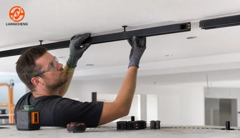
The rail should be fixed to the ceiling by first inserting the wired live end feed into the rail, then lifting the rail onto the marked line and fastening it at the planned fixing points. Many surface-mounted rails are fixed through pre-drilled holes in the profile base or through mounting clips that are attached to the ceiling first and then snap onto the rail. Clips allow the rail to be positioned and adjusted along the line before final tightening.
Screws should be tightened until the rail sits firmly against the ceiling without distorting the profile. Over-tightening can bend the aluminum and change the internal slot dimensions, which makes adapters hard to insert or causes poor contact. After fixing, the rail should be checked along its length with a straightedge or laser line to confirm that it is straight and level.
Step 9: How are track rail runs joined and finished?
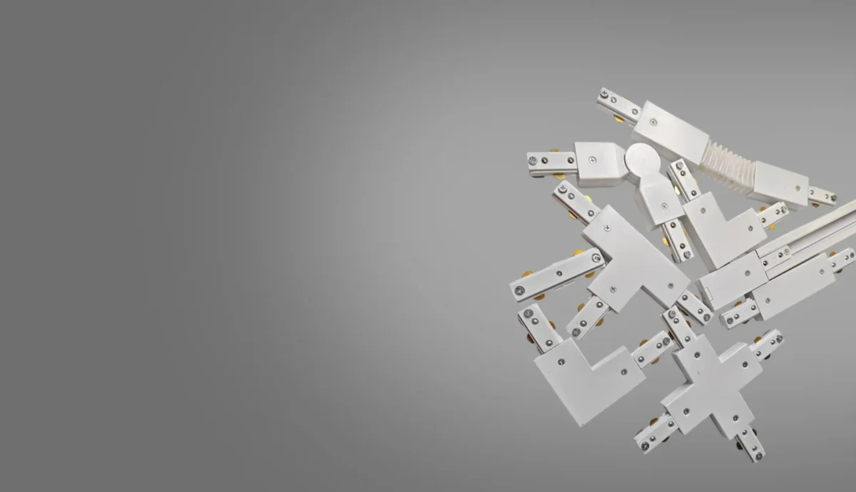
Track rail runs are joined with connectors that both align the profiles mechanically and connect the conductors electrically. Straight joiners connect two rails in a line, L or corner connectors turn the run by 90 degrees, T connectors create a branch, cross connectors create an intersection, and flexible connectors allow angles that are not 90 degrees. Each connector must be inserted fully into both rails and locked as specified, with a fixing point on each side of the joint so the joint carries no load.
Corner, T and cross connectors have a defined conductor orientation, so on multi-circuit rails the installer must check that the neutral and circuit positions continue correctly through the connector. Every open rail end must be closed with an end cap that insulates the conductors and finishes the profile. Planning connectors with the layout is explained in more detail in the track lighting rail dimensions and size guide.
Step 10: How should track heads be installed and the system tested?
Track heads should be installed by inserting each adapter into the rail in the correct orientation, turning the locking lever until it is fully engaged, and selecting the required circuit on multi-circuit adapters. Most adapters have a marking that must face the neutral or earth side of the rail; inserting an adapter the wrong way round either prevents locking or connects it incorrectly. The fixtures should then be aimed roughly before power is restored.
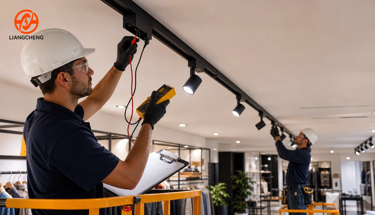
Testing should include visual inspection of all joints, end caps and fixings, continuity of the protective earth from the feed to the far end of the run, an insulation resistance test performed with sensitive drivers and fixtures disconnected, and a functional test of every circuit after power is restored. On multi-circuit rails, each circuit should be switched separately to confirm that the correct fixture group responds. Final aiming and commissioning are done with the lights on and, ideally, with the merchandise or artwork in place.
How many fixtures can one surface-mounted track rail carry?
The number of fixtures one track rail can carry is limited by the rail’s current rating per circuit, the rating of the feed and connectors, the circuit breaker, and the mechanical load capacity of the rail and fixings. Many mains-voltage track rails are rated for roughly 10 to 16 amperes per circuit, but the actual rating printed on the product and its documentation must be used. To check the electrical load, add the input wattage of all fixtures on a circuit, divide by the supply voltage to obtain the current, and keep it comfortably below the lowest rating in the circuit.
For example, twenty 30 W LED track spotlights on a 230 V circuit draw about 2.6 A, which is well within a typical rail rating, while the same number of fixtures on a 120 V circuit draw about 5 A. Mechanical load is usually the tighter limit for heavy fixtures and pendants, which is why fixing spacing and anchor choice matter as much as electrical capacity.
Which track lights are compatible with a surface-mounted rail?
Track lights are compatible with a surface-mounted rail only when their adapters match the rail’s profile family and conductor layout. Rail systems are often grouped by profile families such as H, J and L types for multi-circuit rails, and by proprietary profiles for single-circuit 2-wire and 3-wire rails. A rail and an adapter can look similar while differing in slot width, contact position or earth arrangement, which leads to poor contact, overheating or no earth connection.
Compatibility should be confirmed with physical samples before an order is placed: insert the adapter, lock it, check that it seats firmly, and confirm electrical contact on each circuit. Buyers who source rails and track heads from different suppliers should request the rail’s cross-section drawing and test the adapters on a sample. The H-type vs J-type vs L-type compatibility guide and the track light adapter compatibility checklist explain these checks in detail.
What are the common specifications of surface-mounted track rails?
Surface-mounted track rails share a set of common specifications that buyers and installers should confirm before ordering. The table below summarizes typical values; exact figures depend on the specific product.
| Specification | Common options |
|---|---|
| System type | 2-wire, 3-wire, 4-wire (three circuit), 6-wire |
| Standard lengths | 1 m, 1.5 m, 2 m, 3 m; custom lengths on request |
| Material | Extruded 6063 aluminum alloy with copper conductors and insulating inserts |
| Fertig | Powder-coated or anodized; black, white, silver and custom colors |
| Voltage | Mains voltage, typically 100–240 V AC depending on market |
| Current rating | Commonly around 10–16 A per circuit, as stated by the manufacturer |
| Profile size | Varies by system; slim single-circuit to larger multi-circuit profiles |
| Zubehör | Live end and middle feeds, joiners, L/T/X and flexible connectors, end caps, clips, suspension kits |
Material and profile quality affect installation as much as appearance. A straight, accurately extruded rail with consistent conductor positions makes joints align and adapters lock reliably. The guide to judging track rail quality explains what to inspect.
What are the advantages and limitations of surface-mounted track rails?
The main advantages of surface-mounted track rails are fast installation, no ceiling cutouts, easy relocation of fixtures, simple maintenance and lower installation cost than recessed or suspended systems. Surface mounting also suits concrete and existing ceilings where cutting a recess is difficult or not permitted, and it allows the lighting layout to change with displays, tenants or exhibitions.
The main limitations are that the rail remains visible, which may not suit minimalist interiors, and that the fixtures sit close to the ceiling, which can be a disadvantage in very high spaces where a suspended rail would bring the lights closer to the task. Surface mounting also depends on a flat ceiling; uneven ceilings make straight alignment harder and may require packing or adjustable clips.
Which projects are best suited to surface-mounted track rails?
Surface-mounted track rails are best suited to projects that need flexible accent lighting and fast installation. Typical applications include fashion and retail stores, supermarkets and specialty shops, galleries and museums, showrooms, hotel lobbies and corridors, restaurants and cafes, offices and co-working spaces, and residential kitchens and living areas. They are especially effective in refurbishment projects where the ceiling cannot be opened.
In retail, a surface-mounted rail lets merchandisers re-aim lights each time displays change. In galleries, multi-circuit rails let curators switch or dim different walls separately. In hospitality and offices, surface-mounted rails provide adjustable lighting without the coordination needed for recessed ceiling details. Design examples are described in the article on how to design track lighting for fashion retail stores.
What are the most common surface-mounted track rail installation mistakes?
The most common surface-mounted track rail installation mistake is mixing components from different rail systems, which leads to loose joints, wrong conductor connections and adapters that do not lock. The second most common mistake is connecting the feed to the wrong terminals on multi-circuit rails, so fixtures appear on the wrong switch or the neutral is not continuous.
Other frequent mistakes include using too few fixings or plastic plugs in plasterboard, leaving burrs after cutting, forgetting end caps, placing joints without support on both sides, over-tightening screws so the profile deforms, ignoring the adapter orientation marking, and overloading a circuit with too many fixtures. Each of these mistakes can be avoided with a complete matching component set, a marked layout and the testing sequence described above. Flicker and contact problems that appear after installation are covered in the track light flicker troubleshooting guide.
What should buyers check when purchasing surface-mounted track rails for installation projects?
Buyers purchasing surface-mounted track rails for installation projects should check system completeness, compatibility, certification, quality consistency and packaging, not only the rail price. A rail is only installable when the feeds, joiners, corner connectors, end caps, clips and adapters are all available in the same system and finish, so the quotation should include a full bill of materials for each run.
- System type, profile drawing and conductor layout
- Standard lengths and whether site cutting is permitted
- Current rating per circuit and voltage range
- Full accessory range in the same finish
- Adapter compatibility samples with the track heads to be used
- Certifications required for the target market
- Installation instructions and terminal diagrams in the required language
- Protective packaging for long rails to prevent bending and scratches
- Batch consistency of color, dimensions and conductor position
Additional sourcing guidance is available in the lighting track rail buying guide and the track rail RFQ checklist.
Frequently asked questions
Can I install a surface-mounted track rail myself?
The mechanical mounting of a surface-mounted track rail can be done by a competent installer, but the connection to mains power should be made by a qualified electrician in line with local regulations. In many regions, new lighting circuits or changes to fixed wiring legally require a licensed electrician.
How far apart should track rail fixings be?
Track rail fixing spacing should follow the manufacturer’s instructions. A common practice is to fix the rail at intervals of about one meter or less, with fixings near each end and on both sides of every joiner, and to reduce the spacing for heavy fixtures or pendants.
Can a surface-mounted track rail be installed on a wall?
Many surface-mounted track rails can be installed on walls when the manufacturer approves it. Wall mounting requires attention to fixture aiming, glare and adapter orientation, and the rail must be fixed securely enough to carry fixtures that project away from the wall.
Where should the power feed be located on a track rail?
The power feed is usually located at one end of a run with a live end feed, or at a point along the run with a middle feed. A middle feed is preferable for long runs or when the supply cable is in the center of the room, because it splits the load in two directions.
Can different brands of track heads be used on one rail?
Different track heads can only be used on one rail if their adapters match the rail’s profile family and conductor layout. Compatibility should always be confirmed by testing physical samples, because similar-looking adapters can differ in contact position or earth connection.
Source surface-mounted track lighting rails from Liangcheng Lighting
Liangcheng Lighting manufactures aluminum track lighting rails and complete accessory systems for wholesale, OEM and project customers, including 2-wire aluminum track rails, 3-circuit aluminum track rails and 6-circuit aluminum track rails with matching feeds, connectors, end caps and mounting accessories. We support custom lengths, colors, finishes, private-label packaging and installation documentation for distributors, lighting brands and contractors. Browse our full track rail product range, see typical Anwendungen and learn more about Liangcheng Lighting.
Need surface-mounted track rails for your next project or product line? Send your rail system type, lengths, colors, quantities and target market through the Liangcheng Lighting contact page. Our team will recommend the right rail and accessory set, provide drawings and samples for compatibility testing, and prepare a wholesale or custom quotation for your order.
Benötigen Sie individuelle Schienensystemlösungen?
Kontaktieren Sie Liangcheng Lighting für OEM/ODM Aluminium-Schienenlösungen und professionelle Beleuchtungsunterstützung.
Bezogen