







Estimated reading time: 13 minutes
A 3-wire track rail is a lighting track with three documented conductive paths inside an insulated aluminum profile. In a common single-circuit arrangement, those paths serve line, neutral, and protective earth. A matching adapter connects a track light to the conductors while its mechanical lock holds the fixture securely. However, the name is not a universal wiring standard. The terminal schedule, profile geometry, grounding method, ratings, and matching accessories for the exact product family always control.
The most important practical point is that 3-wire does not mean 3-circuit. Most 3-wire systems are designed for one switched lighting group with a dedicated safety-earth path. Buyers who need several independently controlled groups should specify circuit count separately. This guide explains how a 3-wire system works, how to identify one, which parts form a complete installation, and what distributors and project buyers should include in a wholesale specification.
What is inside a 3-wire track rail?
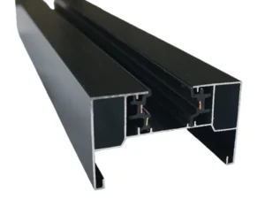
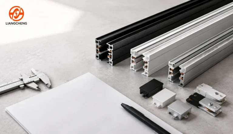
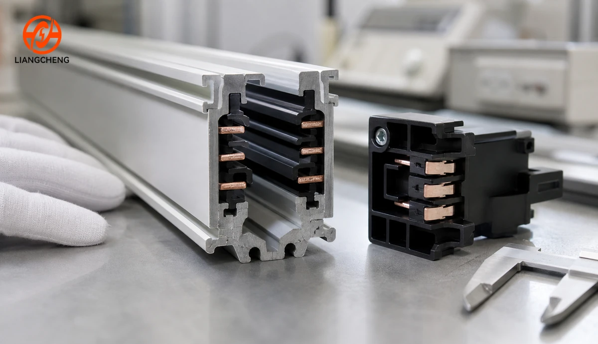
The rail begins with an extruded metal body. Aluminum is widely used because it combines low weight, dimensional control, corrosion resistance, and a clean finished appearance. Inside the profile, insulated carriers hold the conductive strips in fixed positions. The opening accepts only an adapter designed around the same mechanical and electrical interface.
A typical product family contains these functional elements:
- Structural profile: the straight aluminum body that supports fixtures and accessories.
- Insulation: molded or extruded material that separates live conductors from the profile and from one another.
- Conductive paths: three continuous contacts with functions defined by the system drawing.
- Keyed channel: geometry that controls adapter position and orientation.
- Mechanical edges: surfaces that support the adapter lock and fixture load.
- Mounting features: holes, slots, clips, suspension points, or recessed flanges according to the installation type.
Small dimensional differences matter. Two rails can look alike from a room and still have different channel widths, contact positions, keying, or locking details. For that reason, conductor count is only the beginning of compatibility checking. The dimensional topics in the track lighting rail size guide help buyers prepare the measurements needed for a new or replacement system.
What do the three conductors do?
In many line-voltage, single-circuit systems, one path supplies line, one supplies neutral, and one provides protective earth. The earth path supports fault protection when the rail, feed, adapter, fixture, and installation are designed for that arrangement. This common layout explains why 3-wire rail is frequently selected for commercial track lighting that uses metal-bodied fixtures.
It is still unsafe to assign functions only from the product name, conductor color, or appearance. Terminology varies between markets and manufacturers. A technical drawing should identify every terminal, the required supply, polarity or orientation rules, and the approved grounding arrangement. Local electrical requirements and the instructions supplied with the exact system also apply.
The aluminum profile must not be assumed to be an earth conductor unless the product documentation explicitly says so. Protective continuity depends on designed contact points and correct assembly. Paint, anodizing, loose joints, improvised screws, or unrelated accessories can interrupt a path that appears continuous visually.
Does 3-wire track rail provide three lighting circuits?
No. Wire count and circuit count describe different things. A conductor is a physical current-carrying or safety path. A circuit is a complete electrical path with its own protection and control arrangement. A common 3-wire track rail carries one line, one neutral, and one protective-earth path, so all compatible fixtures on that run normally operate as one controlled group.
A multi-circuit rail has additional conductors, feeds, and selectable adapters specifically designed to divide fixtures into independently controlled groups. If separate display zones, schedules, or scenes are required, place that need in the electrical brief before choosing the rail. The guide to single-circuit and multi-circuit track lighting explains this control decision in detail. For a focused comparison of the two common rail formats, see 2-wire track rail versus 3-wire track rail.
How does power reach a track light?
An approved live-end feed connects the building supply to the internal conductors. When a compatible fixture adapter is inserted in the correct orientation and locked, spring contacts press against the matching conductive paths. The adapter transfers line and neutral to the driver and establishes the documented protective connection. Mechanical tabs or cams secure the fixture to the rail.
This interface must satisfy several requirements at the same time: sufficient contact pressure, stable engagement, correct polarity, reliable grounding where required, mechanical retention, thermal performance, and safe creepage and clearance. An adapter that can be forced into a channel is not necessarily compatible. Poor engagement may cause intermittent operation, arcing, overheating, weak grounding, or a fixture that can fall.
Use track heads and adapters approved for the exact rail family. The overview of lights compatible with 3-wire track rail covers fixture selection without treating visual similarity as proof.
How can an existing 3-wire rail be identified?
Start with documentation. Look for a product label, model number, installation sheet, original invoice, project submittal, or marking on the feed and adapter. These records are more reliable than a photograph alone. If documentation is missing, a qualified person should isolate the supply and follow appropriate verification procedures before inspecting the rail.
Record the profile width and height, channel opening, internal keying, conductor positions, feed orientation, adapter contacts, locking feature, voltage marking, current rating, mounting method, finish, and any certification label. Photograph the rail end straight on with a scale visible. Also photograph the feed, joiner, end cap, and both sides of the adapter.
Some markets use family labels such as H, J, or L for common track interfaces. Those labels are useful only when the exact geometry and electrical arrangement are confirmed. Similar-looking parts from different families should not be mixed. The article on H, J, and L track compatibility provides a structured identification method.
What parts make a complete 3-wire track system?
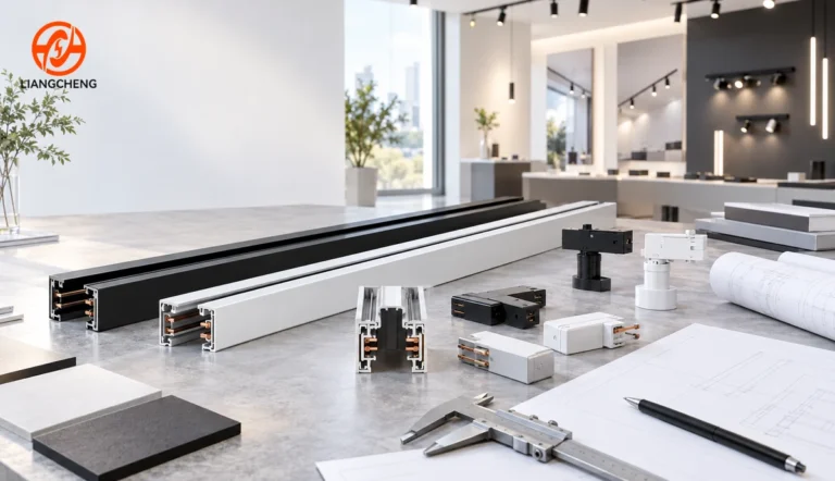
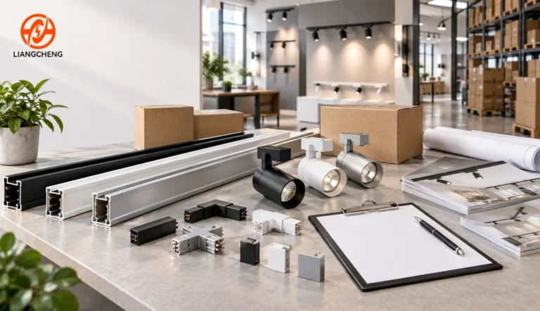
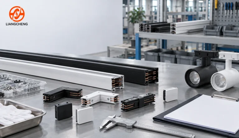
A rail extrusion by itself is not an installable lighting system. The required bill of materials depends on the layout, feed position, mounting style, and number of track heads. A typical project may need straight rail sections, live-end feeds, end caps, straight joiners, corner connectors, suspension kits or recessed mounting parts, matching adapters, luminaires, fasteners, and approved control equipment.
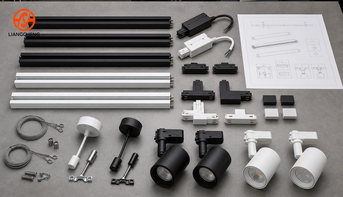
The live-end feed must match the rail orientation and cable entry. Straight joiners extend a run, while electrical joiners continue the conductors across the connection. L, T, or cross connectors create layouts only when their orientation and polarity match the plan. An end cap closes every exposed rail end. Suspension kits require suitable ceiling anchors and correct spacing for the combined rail and fixture load.
For wholesale orders, prepare a layout-based accessory schedule rather than estimating accessories as a percentage of rail length. Count every powered end, dead end, joint, corner, branch, suspension point, and fixture position. Include spares for installation and maintenance where the project requires them.
Where is 3-wire track rail commonly used?
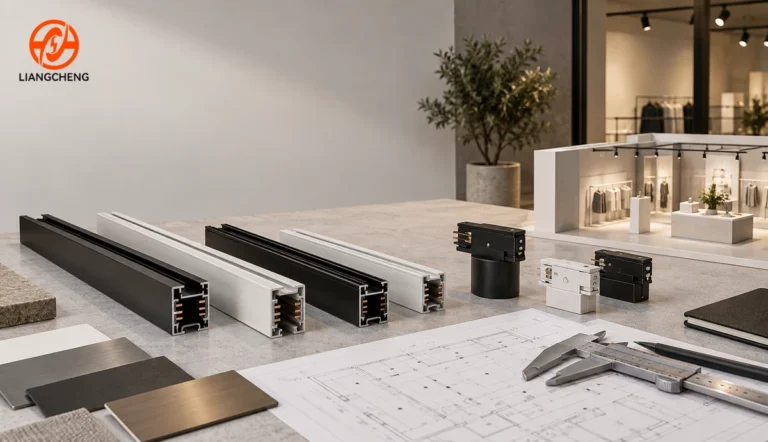
3-wire track rail is commonly specified in retail stores, showrooms, galleries, hospitality spaces, offices, supermarkets, exhibition areas, and residential interiors. It works well where fixture positions or beam directions may change after installation. A long rail can support several adjustable spotlights while keeping the ceiling visually organized.
The system is especially practical for distributors and project contractors who want a repeatable family of rails, connectors, feeds, and fixtures. Stocking a coordinated range reduces mismatched replacements and simplifies quotations. It also enables later changes when merchandising layouts, displays, or furniture move.
A 3-wire system is not automatically the best choice for every project. Consider the required control groups, load, mounting condition, local rules, fixture availability, maintenance plan, and total installed cost. The broader guide on choosing the right track lighting rail can support early project decisions.
Which specifications should buyers compare?
A useful technical comparison goes beyond price per meter. Buyers should request a controlled drawing and data sheet covering the profile dimensions, material, finish, conductor material and cross-section, insulation, rated voltage, rated current, frequency, operating temperature, mounting options, maximum mechanical load, accessory family, adapter interface, and packaging.
Confirm standard lengths and cutting tolerances. Common project lengths may be supplied as factory-finished sections, but exact availability depends on production, coating, and transport limits. Long rails need packaging that controls bowing, twisting, scratching, and crushed ends. A small change in straightness can become obvious after several sections are aligned on a ceiling.
Finish specifications should state color reference, surface treatment, gloss level where important, and acceptance tolerance. Black, white, and natural metal finishes are common, but project colors may be possible for suitable quantities. Rails, feeds, joiners, end caps, adapters, and fixture bodies should be reviewed together because nominally identical colors can look different across materials and batches.
How should a system be planned before installation?
Begin with a reflected ceiling plan showing each rail run, feed point, joint, corner, support point, fixture position, aiming direction, and control group. Coordinate with sprinklers, air outlets, access panels, beams, ceiling grids, signs, and other services. Allow physical room for feeds and connectors rather than using rail length alone as the finished layout dimension.
Calculate the connected load and consider LED driver inrush current, not only steady-state wattage. Confirm protective devices and controls with the project electrical designer. If dimming is required, verify the complete chain: control device, wiring method, driver, luminaire, and track arrangement. A 3-wire label alone does not establish dimming compatibility.
Select the mounting method early. Surface mounting keeps the profile visible and requires secure fixing to the substrate. Suspension can solve high-ceiling or open-ceiling conditions but adds cable and leveling requirements. Recessed installation needs a coordinated cutout, trim detail, ceiling depth, and access strategy. Any custom cut, drilled hole, or connector position should follow approved drawings.
What happens during installation and commissioning?
Installation should be completed by qualified personnel according to local requirements and the manufacturer instructions. The supply must be isolated and verified before electrical work. The installer checks the substrate, lays out fixing points, maintains rail alignment, connects the approved feed, installs connectors in the correct orientation, closes exposed ends, and locks compatible adapters fully into position.
Before energizing, inspect conductor condition, terminal tightness, polarity or orientation, protective continuity, connector engagement, end protection, support spacing, and fixture retention. Testing should follow the system documentation and applicable rules. After energizing, verify stable operation across the full run, correct switching, dimming behavior where specified, and the absence of unusual heat, noise, flicker, or intermittent contact.
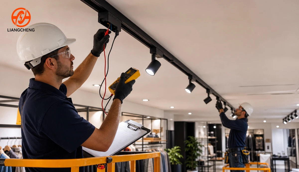
Keep an installation record with rail and fixture models, layout drawings, circuit information, test results, batch references, spare parts, and maintenance instructions. This record makes future additions and fault diagnosis much safer than relying on appearance.
What problems can occur and how are they investigated?
If one fixture does not operate, isolate power and confirm that the adapter belongs to the rail family, is oriented correctly, and is fully locked. A qualified technician can then inspect the adapter contacts, driver, luminaire, and rail at that position. Moving a suspect fixture without a safe procedure can conceal an intermittent contact fault.
If several fixtures fail beyond a joint, investigate the connector orientation, engagement, conductor continuity, and upstream feed. If lights flicker, look for loose contacts, damaged conductors, incompatible dimming equipment, excessive load, driver behavior, or unstable supply. Discoloration, odor, deformation, or unusual heat requires immediate isolation and professional assessment.
Mechanical issues also matter. A rail that sags, twists, or separates at joints may have inadequate support, unsuitable anchors, excessive fixture load, or shipping damage. Do not solve poor engagement by bending contacts or forcing adapters. Replace damaged or incompatible components with approved parts.
How should distributors specify a wholesale order?
A distributor request should define the destination market, intended electrical arrangement, rated supply, required grounding, rail profile, standard and custom lengths, mounting type, finish, quantity, accessory schedule, matching adapter, compatible luminaires, packaging, labeling, documentation, and delivery plan. Send a drawing or physical sample when matching an existing system.
Request a complete pre-production sample rather than only a short extrusion. The sample kit should include the chosen rail, feed, joiner, end cap, mounting part, adapter, and luminaire. Assemble it using the intended installation method and verify fit, orientation, locking, electrical operation, finish consistency, and packaging protection.
For production inspection, agree on dimensional checkpoints, straightness, twist, conductor position, insulation condition, surface quality, color, connector fit, adapter insertion and removal, fixture retention, electrical checks, marking, and pack quantity. Retain the approved sample and drawing revision. Changes to the profile, conductor, insulation, feed, connector, or adapter should trigger compatibility review.
Can a 3-wire track rail be customized?
Customization can include rail length, cutting, mounting holes, finish, branding, packaging, labels, accessory combinations, and coordinated fixtures, subject to engineering review and order quantity. Electrical geometry should not be changed casually because conductor positions, insulation, feeds, and adapters operate as one system.
A productive custom program begins with the target application and acceptance criteria. Provide drawings, samples, forecast volume, destination requirements, finish references, packaging needs, and expected tests. Prototype the complete system, approve a golden sample, then control production against the agreed revision. Liangcheng offers more detail in its overview of custom LED track rail solutions.
What should a final purchasing checklist include?
Before confirming an order, place the technical, commercial, and logistics requirements in one controlled checklist. The technical portion should identify the rail drawing revision, conductor schedule, rated voltage and current, grounding method, profile tolerances, standard lengths, cutting plan, mounting configuration, finishes, and compatible component codes. The commercial portion should state quantities by item, spare allowance, sample approval, production lead time, inspection stage, and agreed documentation.
The logistics portion should define piece protection, inner packs, carton or crate construction, labels, pallet limits, moisture protection where needed, and container loading method. Long aluminum profiles can be damaged even when the carton exterior appears intact. End reinforcement and internal separation help protect the rail opening, finish, and straightness. Buyers should also agree on how mixed accessory cartons are identified so installers can find feeds, connectors, end caps, and mounting parts quickly.
Review the final quantity against the ceiling layout one more time. Separate rail meters from the number of physical sections, because joints and packaging depend on section count. Check left-hand and right-hand or polarity-sensitive connectors where the system uses them. Confirm that every open end has an end cap and every powered run has the correct feed. A small scheduled spare quantity can reduce project delays caused by site changes or accidental damage.
How can lifecycle cost be controlled?
The lowest rail price does not always produce the lowest installed cost. A coordinated product family can reduce sorting, rework, return freight, installation delays, and replacement uncertainty. Clear model marking and retained drawings make it easier to supply additions later. Standardizing finishes, lengths, and fixture adapters across related projects can also simplify distributor stock.
Plan maintenance access before the ceiling is closed. Keep compatible spare adapters, feeds, joiners, and several representative luminaires when continuity of appearance is important. Record the production batch and approved finish. During periodic inspection, look for loose fixtures, damaged end protection, displaced joints, unusual heat, discoloration, or changes made by later trades. Any electrical fault should be assessed by qualified personnel with the supply isolated.
When a project will expand in phases, confirm that the selected family and finish can be supplied across the expected schedule. Forecasting does not guarantee permanent compatibility, but it gives the supplier time to manage materials and revision control. For large programs, an agreed golden sample, retained control drawings, and batch traceability provide a stronger basis for consistent repeat orders.
Common mistakes to avoid
- Assuming three wires mean three circuits. Define conductor functions and independently controlled groups separately.
- Ordering by appearance. Confirm cross-section, contacts, keying, adapter, feed, and ratings.
- Mixing unrelated components. Treat rail, connectors, adapters, and luminaires as one coordinated family.
- Ignoring accessory quantities. Build the bill of materials from the actual layout.
- Skipping load and inrush review. LED systems must be checked as an electrical installation, not only by fixture wattage.
- Approving only the extrusion. Test a complete sample kit before bulk production.
- Under-specifying packaging. Long profiles need protection from bending, crushing, movement, and surface damage.
Frequently asked questions
Is a 3-wire track rail always line, neutral, and earth?
That is a common arrangement, but it is not safe to assume. Verify the terminal schedule, grounding method, ratings, and installation instructions for the exact product family.
Can any 3-wire track light fit any 3-wire rail?
No. The profile, channel, contact locations, orientation, locking mechanism, grounding feature, and electrical ratings must all match. Similar appearance and the same conductor count do not prove compatibility.
Can a 3-wire rail be cut on site?
Some systems allow cutting when the manufacturer procedure is followed, but the cut must be square, clean, deburred, correctly insulated, and fitted with approved end protection. Factory-cut lengths can simplify quality control for repeated projects.
Can 3-wire track lights be dimmed?
They can be dimmed only when the luminaires, drivers, dimmer or control equipment, wiring arrangement, loading, and rail system are compatible with the selected method. The number of rail conductors does not guarantee dimming.
What should be sent for a replacement quotation?
Send model markings, clear end-view photographs, profile dimensions, conductor positions, feed and adapter photos, voltage and current information, required lengths, finish, quantity, destination, and any original drawing or sample.
Source a coordinated 3-wire track rail system
A reliable 3-wire track rail project depends on more than the extrusion. Conductor functions, profile geometry, feeds, connectors, mounting parts, adapters, fixtures, testing, and packaging must be coordinated from the first specification through final installation.
Liangcheng Lighting provides wholesale and custom track lighting rail solutions for distributors, lighting brands, contractors, and commercial projects. The team can coordinate rail profiles, lengths, finishes, accessories, compatible adapters, track lights, branding, packaging, samples, and production inspection. Explore the Liangcheng Lighting website for more product and technical information, then send your market, drawing or sample, required quantity, finish, accessory list, and application details to request a B2B quotation.
Need Custom Track Lighting Solutions?
Contact Liangcheng Lighting for OEM/ODM aluminum track rail solutions and professional lighting support.